

Content last revised on September 28, 2026
PMH150CS1D060 Circuit Protection & Reliability: Calibrating Auxiliary Emitter Return Trace Separation
Before disconnecting the power stage, isolate the equipment, verify that the DC link is discharged, and compare the installed module marking with PMH150CS1D060 on the equipment parts list. Record the terminal connections and mounting arrangement before removal; matching the current rating alone does not establish electrical or mechanical compatibility.
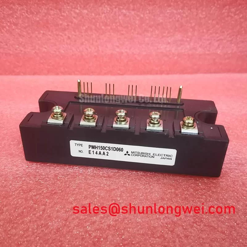
The PMH150CS1D060 is a Mitsubishi Electric intelligent power module with a 600.0 V rated voltage and 150.0 A rated current. These identify the component’s basic rating class, but do not establish its permissible continuous operating point without the applicable temperature conditions, switching limits, cooling arrangement, and control requirements.
Begin the interface assessment with the original circuit diagram and terminal assignment. An IPM should not be treated as a bare IGBT with unrestricted access to its internal gate circuit. For PMH150CS1D060, verify the documented control inputs, reference terminals, auxiliary supply connections, and protection outputs before modifying wiring. A dedicated Kelvin emitter terminal is not established by the rating and device-type information above, so return separation must follow the actual terminal diagram rather than an assumed internal structure.
Design Consideration: Where the documented interface provides a separate control reference, route its return so that main power current does not flow through the same conductor segment. Shared impedance can shift the reference seen by the control circuitry during switching. The practical objective is to reduce coupling between the high-current commutation path and the low-level command path, while preserving the grounding arrangement specified for the module and controller.
Inspect the complete return path, including board traces, connectors, cable shields, and supply decoupling connections. A short trace beside the module does not resolve a shared return farther upstream. Keep command signals close to their corresponding reference conductors and separate them from high-current switching loops where the equipment layout permits. Required spacing must be established from the system voltage, insulation arrangement, environment, and applicable equipment requirements; the module’s voltage rating does not define board clearance.
If intermittent protection events accompany switching transitions, compare the control supply, input signal, reference potential, and fault output using suitable isolated measurement equipment. Trigger the capture on the fault event and examine the preceding waveform rather than only the controller’s recorded alarm. Reference movement, supply disturbance, or coupled noise can produce similar symptoms, so each explanation needs measurement against a known-good channel or the documented operating limits.
Miller coupling is relevant to IGBT switching behavior, but external gate damping, negative bias, or active clamping should not be added to an IPM interface without manufacturer support. The accessible control interface and internal driver architecture determine which interventions are permissible. Consult Mitsubishi Electric Power Semiconductors & High-Power Modules for manufacturer documentation, then apply only the instructions corresponding to the exact device.
Transient Dynamics & Electrical Design: Transient Thermal Impedance on PMH150CS1D060
A pulsed overload assessment starts with the load profile and cooling conditions, not the 150.0 A rating in isolation. For a heavy-duty variable frequency AC motor drive evaluation, obtain the acceleration duty, overload duration, repetition pattern, switching conditions, and measured case temperature. This is a potential integration assessment, not a statement that PMH150CS1D060 is approved for every drive operating at that current.
Design Consideration: Junction temperature responds differently to an isolated pulse and to repeated overloads that leave residual heat in the assembly. The applicable junction-to-case transient thermal impedance curve is therefore necessary for estimating temperature rise during short events. A steady-state thermal resistance alone cannot describe the complete response, and heatsink temperature should not be substituted directly for junction temperature.
An Engineering Calculation using a multi-RC thermal model requires manufacturer-provided coefficients or a validated fit to the device’s published transient response. For a defined loss pulse, the estimated junction rise follows the pulse power multiplied by the transient thermal impedance at the relevant duration, with the appropriate case boundary temperature included. Repetitive and variable-power operation requires accounting for the preceding thermal history. Without the model-specific thermal data and loss characteristics, a numerical peak junction temperature or overload margin would be unsupported.
Keep the thermal model boundaries consistent. A model representing junction-to-case behavior does not automatically include the interface material, heatsink, airflow, or coolant path. Case temperature measurements also need the location and method specified in the device documentation. During validation, compare the calculated response with measured temperatures and confirm that the measurement arrangement does not disturb the thermal interface.
During replacement, inspect the module contact surface and heatsink for contamination, damage, and uneven contact. Select the thermal interface material and application method from the approved assembly instructions. No fixed interface thickness or screw torque is established here for PMH150CS1D060. A cross-pattern tightening sequence may help distribute seating force where compatible with the documented mounting procedure, but the fastener specification, tightening stages, and final torque remain assembly-specific.
Do not apply press-pack clamping procedures, disc-spring preload settings, or double-sided cooling assumptions to this module without a corresponding mechanical specification. The device type alone establishes none of those requirements. For procurement, obtain the mechanical drawing alongside the electrical documentation so that mounting holes, terminal access, contact surfaces, and enclosure clearances can be checked before installation.
PMH150CS1D060 Thermal-Electrical Optimization: Derating Guidelines and Mismatched Parameter Practical Tuning
Assess derating against the complete operating envelope: bus voltage, current waveform, switching losses, case temperature, cooling performance, and protection behavior. The 600.0 V and 150.0 A ratings are not simultaneous guarantees for every operating condition. Designers should verify the manufacturer’s rating conditions and safe operating limits before accepting a replacement or changing the equipment duty cycle.
Design Consideration: Static and dynamic current sharing are separate questions when power stages are evaluated for parallel operation. A positive temperature coefficient of on-state voltage can assist sharing only within the operating region where the applicable device characteristic demonstrates that behavior. It must not be assumed for PMH150CS1D060 from its model number, nor used as evidence that parallel operation is supported. Such an arrangement requires manufacturer guidance and system-level validation.
Where a documented system uses multiple coordinated power paths, compare conductor resistance, connection quality, thermal contact, and cooling distribution. Dynamic imbalance also depends on switching behavior and interconnect impedance. Equal command timing does not ensure equal current when the physical paths differ. For an IPM, preserve the specified control interface rather than attempting to match inaccessible internal gate loops through external modifications.
Engineering Recommendation: Keep corresponding commutation paths physically balanced to reduce unequal switching overshoot, and verify the resulting voltage margin through an appropriately protected double-pulse test where the module documentation permits that test arrangement.
Cross-model comparison should distinguish a different design option from a service replacement. The CM300DXDX1-24A can be considered in a separate power-module comparison, but its listing does not establish interchangeability with PMH150CS1D060. Compare documented topology, drive requirements, protection functions, mounting geometry, terminal arrangement, and thermal characteristics before considering a redesigned assembly. A different module cannot be accepted solely because its headline rating appears sufficient.
The same discipline applies to the front end and associated switching stages. If the equipment schematic identifies a separate semiconductor switching stage, the CM100DY-12E may be examined as a complementary circuit candidate using its own documentation. That reference is not evidence that it is a rectifier or a required companion to PMH150CS1D060. Confirm the actual rectification, DC-link charging, braking, and inverter functions from the equipment schematic before assessing component coordination.
When investigating uneven phase behavior, compare current waveforms and thermal conditions under matched loads. Check sensors, connectors, command timing, and cooling before attributing the difference to the module. Preserve the test conditions in the service record so that a later measurement can distinguish an assembly change from a change in operating duty.
Preventing Spurious Faults: DC-Bus Operating Voltage Headroom Derating Guidelines for PMH150CS1D060
Measure the DC-link operating range and the switching peak at the relevant power terminals before deciding that voltage headroom is adequate. The 600.0 V rated voltage is not a recommended nominal bus setting. Supply tolerance, regenerative operation, switching overshoot, and abnormal operating states must be evaluated against the applicable device limits and the equipment’s protection strategy.
Design Consideration: Reduce parasitic inductance in the commutation loop to limit turn-off overshoot, while keeping the arrangement compatible with insulation and mechanical requirements. Review the proximity of the local DC-link connection, opposing current paths, and terminal joints. A laminated bus structure can be assessed where the assembly supports it, but geometry alone does not prove acceptable transient behavior. Confirm performance under representative current, temperature, and switching conditions.
A protection indication during deceleration may coincide with regenerative bus rise, control-supply disturbance, or another system event. Capture the bus voltage and protection signals together, then compare their timing with the operating sequence. Check the braking or regeneration circuit against the equipment documentation. Do not suppress an alarm or increase a protection threshold simply to eliminate an intermittent trip.
Altitude and radiation-related reliability require a separate evidence-based assessment. The available PMH150CS1D060 ratings do not establish a single-event burnout threshold, a failure-in-time rate, or an altitude-dependent bus derating curve. If the installation requires such analysis, obtain applicable manufacturer reliability guidance and the equipment’s environmental requirements. Generic neutron-flux relationships cannot establish this module’s failure probability.
The Mitsubishi Electric Global Semiconductor Device Technologies resource provides manufacturer context for semiconductor technologies; it does not replace model-specific reliability documentation. Keep semiconductor voltage stress, cooling performance, and equipment insulation requirements as distinct checks rather than combining them into an unsupported derating percentage.
For recurring faults, use IGBT Design & Integration as supporting guidance for the layout, thermal, and topology review, while retaining the PMH150CS1D060 documentation as the authority for component limits. Before returning the equipment to service, verify control-supply stability, protection reporting, thermal contact, and switching-voltage margins under the intended duty.