
Shunlongwei Co. ltd.
IGBT Module / LCD Display Distributor
Customer Service
+86-755-8273 2562
IGBT Module / LCD Display Distributor
OEMs mostly outsource the design and production of on-board Electronic control units (ECUs) to component manufacturers. During vehicle integration, the electrical system is connected to an organic whole with multiple ECUs and multiple nodes, making its functions and performance more complete. . At present, CAN bus, as one of the most widely used field buses in the world, has won the affirmation of users for its excellent reliability and stability, and is also widely used in the communication connection between ECUs. With the increasing complexity of the system, its network The reliability requirements of communication quality have become increasingly prominent, which requires us to establish a reliable system to ensure the communication quality of bus products.
Based on the test specifications of the international standard ISO 11898, it has been recognized by many manufacturers and institutions. The test results are:
Can fully evaluate the resistance, capacitance, communication level and timing data of CAN nodes;
It can verify the performance of the circuit design and driving capability of the physical layer of the CAN node;
Provide an important basis for confirming the quality of bus products and improving existing designs.
Today, I will explain in detail the CAN bus physical layer conformance test item of ISO 11898 – CAN bus voltage test.
CAN bus voltage test
CAN bus voltage test is divided into two categories: CAN bus recessive voltage test and CAN bus dominant voltage test.
1. CAN bus recessive voltage test
The test principle of the CAN bus recessive voltage test is shown in Figure 1. In the actual test, a high-precision oscilloscope or a CAN bus analyzer is commonly used to measure the voltage of the CAN bus.
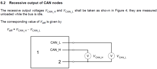
Figure 1 ISO 11898-2-2003 CAN bus recessive voltage test
Measure the voltage of CAN_H and CAN_L to the signal ground (port 2 in Figure 1) and calculate the voltage value of CAN_diff (CAN_H – CAN_L) when the ECU is idle without load (that is, remove the terminal resistance), and compare it with the voltage in Figure 2. Compare the range of voltage evaluation to determine whether it meets the standard.

Figure 2 ISO 11898-2-2003 CAN bus recessive voltage test evaluation criteria
2. CAN bus dominant voltage test
The test principle of the CAN bus dominant voltage test is shown in Figure 3. In the actual test, a high-precision oscilloscope or a CAN bus analyzer is commonly used to measure the voltage of the CAN bus.
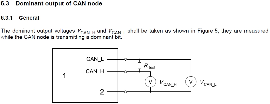
Figure 3 ISO 11898-2-2003 Dominant Output Voltage Test
Connect a test resistor between CAN_H and CAN_L of the ECU (Rtest in Figure 3 should be between 100 and 130Ω). If a terminal resistor of 100 to 130Ω has been connected, it is not necessary to connect Rtest. When measuring the dominant bit of the sending message, the voltage of CAN_H and CAN_L to the signal ground (port 2 in Figure 3) and the voltage value of CAN_diff (CAN_H – CAN_L) are calculated, and compared with the voltage evaluation range in Figure 4 to judge whether it meets the standard.
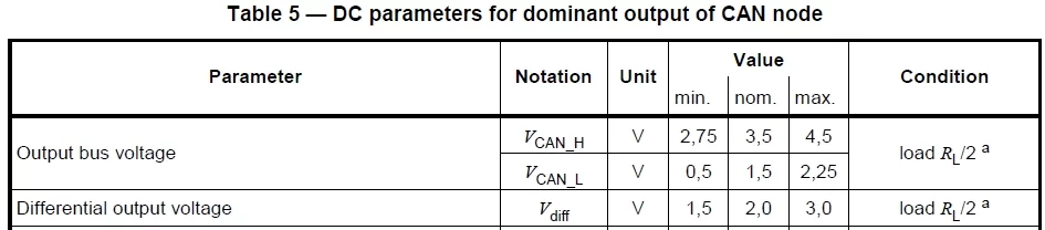
Figure 4 ISO 11898-2-2003 Dominant Output Voltage Test Evaluation Criteria
have to be aware of is:
When testing the voltage values of CAN_H and CAN_L, the CAN_GND (bus signal ground) of the ECU must be drawn out to correctly perform the CAN bus voltage test.
The following is the test result of a car factory’s ECU tested with the ZDS4054 Plus oscilloscope:
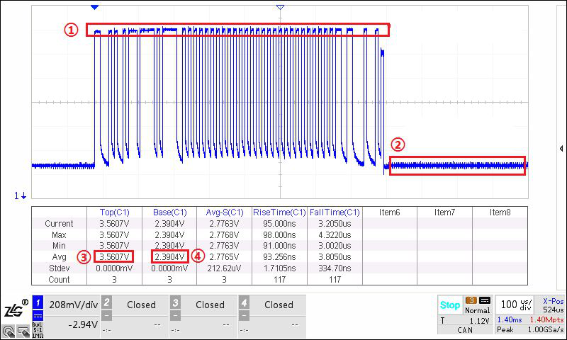
Figure 5 CAN_H one frame message screenshot
In Figure 5, ① in the red box is the CAN_H dominant bit voltage, and its voltage value is as in ③ the value in the red box: 3.56V;
In Fig. 5, ② in the red box is the CAN_H recessive bit voltage, and its voltage value is such as the value in the ④ red box: 2.39V.
The test results meet the evaluation criteria in Figures 2 and 4.
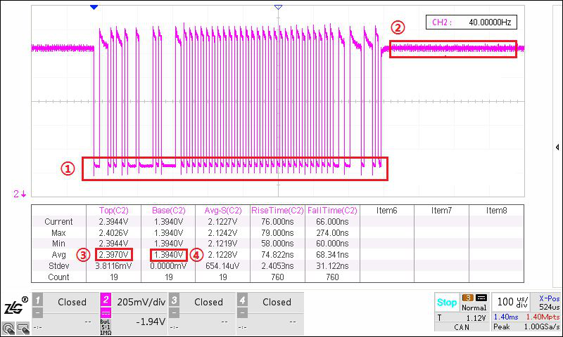
Figure 6 Screenshot of CAN_L one frame message
In Figure 6, ① the red box is the dominant voltage of CAN_L, and its voltage value is as shown in ④ the value in the red box: 1.39V;
In Figure 6, ② the red box is the CAN_L recessive bit voltage, and its voltage value is as shown in ③ the value in the red box: 2.39V.
The test results meet the evaluation criteria in Figures 2 and 4.

Figure 7 CAN_diff one frame message screenshot
In Figure 7, ① the red box is the dominant bit voltage of CAN_diff, and its voltage value is as shown in ③ the value in the red box: 2.14V;
In Figure 7, ② the red box is the recessive bit voltage of CAN_diff, and its voltage value is the value in the ④ red box: 14.60mV.
The test results meet the evaluation criteria in Figures 2 and 4.
Summarize
The output voltage test item introduced in this issue is just one of many conformance tests, which can be manually tested by an oscilloscope or CAN analyzer. In the later test project explanation, we will find that many test items are complicated and time-consuming in the way of manual testing. Under the trend of automated testing, ZLG’s fully automatic CAN conformance testing system – CANDT, can solve the above problems very well. Its test process fully complies with the ISO 11898 standard, and at the same time, it can automatically complete all tests with one key, and export detailed test reports to help CAN automated testing.

Figure 8 CAN Conformance Test System
If you have any questions, you can: 1. Add a small Z WeChat account, and call the official technical hotline of ZLG Ligong Technology·Zhiyuan electronics.


