Content last revised on September 4, 2026
LB150X03 TL03 Display Integration and Bench Diagnostics
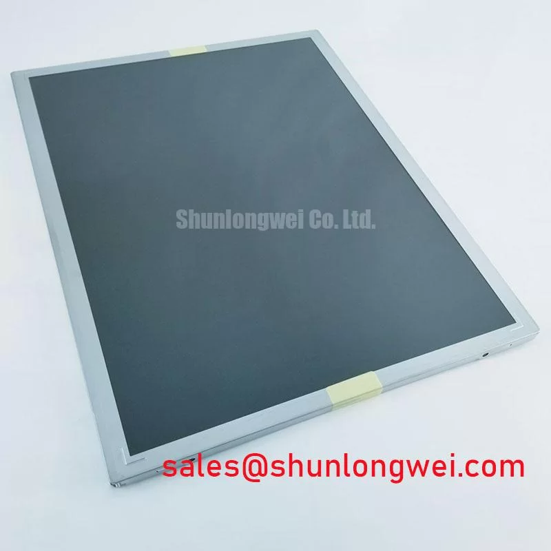
Before reconnecting an LB150X03 TL03, inspect its display connector, flex path, mounting frame, and the original equipment panel label with power removed; this LG 15.0 inch XGA TFT LCD panel must be matched by the host controller’s documented interface, timing, power sequence, and mechanical arrangement.
The panel is intended for equipment displays rather than inverter power switching. Its relevant identity is a 15.0 inch active matrix LCD with 1024 × 768 XGA resolution. The system integrator should verify the original panel documentation for supply voltage, signal pin assignment, backlight requirements, connector position, mounting dimensions, optical grade, and controller compatibility before installation.
| Parameter | Specification Status |
|---|---|
| Model | LB150X03 TL03 |
| Manufacturer | LG |
| Product Type | TFT LCD panel |
| Display Size | 15.0 inch |
| Native Resolution | 1024 × 768 XGA |
| Integration Requirement | Verify original equipment interface, power sequencing, backlight connection, and mechanical fit |
Voltage doubling, motor cable reflections, output reactor selection, and dvdt filtering are inverter output subjects and are not electrical functions of the LB150X03 TL03 LCD panel. A display panel does not switch a DC link, drive a motor phase, or provide a braking path. Applying inverter transient assumptions to its display connector would create an incorrect repair procedure.
For bench evaluation, technicians should instead isolate the display subsystem from the traction inverter and confirm that the display harness is not exposed to traction voltage, motor phase conductors, or high energy switching returns. On low voltage electric material handling equipment, display faults can coexist with inverter faults because both assemblies may share a battery supply and chassis environment, but they remain separate electrical domains.
If the panel shows intermittent image loss, flicker, or a blank raster, inspect the host board output using the known good signal path and the original equipment documentation. Check connector retention, cable strain, panel grounding provisions, and supply sequencing. A waveform that appears distorted at the display interface may indicate a signal integrity or reference return issue, but it does not establish a panel defect without comparison to a verified host signal.
Design Consideration: route display signal cables away from traction motor leads and switching nodes where practical, maintain intended shielding continuity, and verify the installed cable route in the finished machine. This reduces the chance that common mode noise from the traction system is coupled into low level display signalling.
🔧 Bench Diagnostic: Disconnect panel and backlight connections only after the equipment power source has been isolated and stored energy in associated power electronics has been confirmed discharged.
LB150X03 TL03 Mechanical Installation and Environmental Considerations
Heatsink contact pressure, thermal interface material thickness, baseplate flatness, bootstrap capacitors, and high side gate supply integrity apply to power semiconductor assemblies, not to the LB150X03 TL03 display panel. This model should not be treated as an IGBT module and must not be mounted to a heatsink under assumed semiconductor clamping requirements.
The appropriate mechanical concern is panel frame support. The display should be retained only at the positions and with the fastening method defined by the original equipment panel documentation. Uneven frame loading, forced alignment against a warped bezel, or pressure transferred through the active viewing area can damage the panel assembly or introduce visible optical nonuniformity. Designers should verify the enclosure’s flatness, mounting land position, and clearance around the connector before closing the equipment front assembly.
Where the panel is installed in a forklift control display or warehouse vehicle terminal, the surrounding enclosure should be assessed for vibration isolation, cable retention, moisture control, and service access. These are Design Considerations for the complete machine, not official environmental ratings for this specific panel.
For industry context on industrial display integration, engineers can consult the Sharp Display Solutions official portal and Sharp Devices Europe industrial display resources. These sources support general display system evaluation but do not replace the original documentation for the LB150X03 TL03.
LB150X03 TL03 Interface Compatibility and Operational Boundaries
Auxiliary emitter routing, Kelvin emitter separation, gate loop inductance, negative gate bias, and dual IGBT oscillation control do not apply to the LB150X03 TL03. The panel has no collector, emitter, gate, braking transistor, or power switching die accessible to the equipment designer. Its operational boundary is defined by correct display interface integration rather than semiconductor switching limits.
The critical PCB relationship is between the host display controller, the interconnect cable, and the panel input. The replacement panel should have the same documented signal format, connector arrangement, timing expectations, and power sequence as the removed unit. Physical connector mating alone is not sufficient evidence of electrical compatibility.
When a host controller is being evaluated alongside traction electronics, keep the troubleshooting records separated by subsystem. A power stage device such as BSM75GD120DLC is an IGBT module and is not a replacement panel for the LB150X03 TL03. Likewise, BSM75GB120DN2 belongs to a power semiconductor category and requires its own documented drive, protection, thermal, and topology assessment.
For a forklift display replacement, verify the original machine controller’s panel interface before ordering or installation. If the display remains inactive after correct mechanical installation, compare the source supply, enable control, video path, and cable condition with a known good assembly. A single symptom can have more than one cause, including a controller output issue, harness wear, sequencing mismatch, or panel related fault.
LB150X03 TL03 Display and Traction System Integration
Braking resistor sizing and chopper transistor selection are functions of the traction inverter DC link. They are not functions of the LB150X03 TL03 LCD panel and should never be specified from panel model information. The motor’s deceleration energy, battery acceptance behavior, DC link architecture, braking control method, and inverter protection strategy determine whether a braking circuit is required and how it must be validated.
For electric material handling and forklift low voltage traction equipment, engineers should assess display and inverter integration independently. A display mounted near traction electronics should have secure cable routing, strain relief, and an enclosure layout that avoids placing its signal harness alongside high current switching conductors. The final routing should be validated on the actual machine while observing display stability during acceleration, deceleration, charging, and auxiliary load operation.
Where a repair team is also investigating induction heating or resonant power circuits, Resonant Topologies in Home Appliances provides separate topology reference material. It does not define the electrical requirements of the LB150X03 TL03 display.
The service objective is straightforward: retain the original equipment’s documented display interface, avoid applying inverter power design rules to the panel, and validate the installed screen through controlled functional testing of the complete HMI system.