
Shunlongwei Co. ltd.
IGBT Module / LCD Display Distributor
Customer Service
+86-755-8273 2562
IGBT Module / LCD Display Distributor
“Machine vision systems use very short flashes of bright light to produce high-speed images for a variety of data processing applications. For example, fast-moving conveyor belts run through machine vision systems for rapid labeling and defect detection. Infrared and laser LED flashes are commonly used in machine vision for proximity and motion detection. Security systems emit high-speed, imperceptible LED flashes to detect motion, capture and store security images.
“
Machine vision systems use very short flashes of bright light to produce high-speed images for a variety of data processing applications. For example, fast-moving conveyor belts run through machine vision systems for rapid labeling and defect detection. Infrared and laser LED flashes are commonly used in machine vision for proximity and motion detection. Security systems emit high-speed, imperceptible LED flashes to detect motion, capture and store security images.
A challenge with all of these systems is generating very high current and short duration (microsecond) LED camera flash waveforms that can spread out over longer periods of time, say 100 ms to over 1 s. Generating a square wave of short LED flashes at long intervals is not an easy task. The challenge is further exacerbated when the LED (or LED string) drive current rises above 1 A and the LED turn-on time is reduced to a few microseconds. Many high-speed PWM capable LED drivers may not be able to efficiently handle long off-times and short high currents without degrading the square wave quality required to properly handle high-speed images.
Proprietary LED flash
Fortunately, the LT3932 high-speed LED driver can provide machine vision camera flashes for LED strings up to 2 A, with off-times as long as 1 second, 1 hour, 1 day, or more. The special camera flash feature of the LT3932 allows it to keep the output capacitor and control loop charged, even during long off-times. After sampling the state of the output and control loop capacitors, the LT3932 continues to trickle charge these components during long off-times to compensate for leakage currents that are typically present, not accounted for by other LED drivers.
The LT3932’s proprietary flash technology can be extended and drivers can be paralleled to provide higher LED flash currents. The desired glitter shape and integrity remain the same. Figure 1 shows how easy it is to parallel two drivers to support a 3 A camera flash, and designs up to 4 A are possible.
The LED flash requirements for machine vision systems are much higher than what can be achieved with standard PWM dimming drivers. That said, most high-end LED drivers are designed to provide PWM dimming brightness control at PWM frequencies of at least 100 Hz. This is because at lower frequencies, even if the LED waveform is square and repeatable, what the human eye sees is an annoying flicker or strobe. At 100 Hz, the theoretical maximum off-time is about 10 ms. During the 10 ms off time, if designed correctly, the LED driver loses so little output capacitor charge that it starts the control loop in about the same state that ended the last PWM on-pulse. The fast response and ramp-up of the Inductor current and the next LED PWM turn-on pulse can be fast and repeatable with extremely short start-up times. Long off-times (at frequencies below 100 Hz) can cause the output capacitors to lose charge due to leakage, making the LEDs less responsive when they are turned back on.
Parallel LED drivers for higher current
The LED driver acts as a current source, regulating the current sent through the LEDs. Current only flows in a single direction to the output, so multiple LED drivers can be connected in parallel and their currents aggregated through the load. The current source does not need to guard against reverse current flow through a converter, nor does it need to worry about output mismatch. On the other hand, voltage regulators are not inherently good at current sharing. If they are both trying to regulate the output voltage to a certain point, and there is a slight difference in their feedback network, the regulators may draw reverse current.
The LED driver keeps its output current constant regardless of whether other drivers provide additional current and sum it up at the output load. This makes paralleling LED drivers very simple. For example, an LED flash system with two parallel LT3932 LED drivers shown in Figure 1 can efficiently drive 4 LEDs at 3 A with short 10µs pulses spread out over a long period defined by the machine vision system. During the PWM on-time, each LT3932 converter generates half of the total string current; during the PWM off-time, the converter shuts down and saves its output state. The off time can be short or long and has no effect on the repeatability of the flash waveform.

Figure 1. Parallel LT3932 1.5 A LED drivers generate 3 A machine vision LED pulses with long off-time relative to standard PWM dimming frequency.

Figure 2. The 3 A camera flash waveform shown in Figure 1 with paralleled LED drivers looks the same regardless of the PWM off time. The waveforms show that the 10µs pulse after (a) 10 ms and (b) 1 s is the same. The LT3932 LED flash waveforms also look the same after a day or more of PWM off time.
Parallel camera flash applications are almost as simple as a single converter during long off periods. The converter observes the shared output voltage at the end of the last PWM on-pulse and allows the output capacitor to charge to this state and maintain it, even during long off-times. Each converter disconnects its PWM MOSFET from the shared load and supplies current to its output capacitor to compensate for the leaked energy, charging that capacitor to near the final voltage state and holding it. Any leakage from these capacitors during long off-times can be compensated by a small amount of holding current. When the next PWM turn-on pulse begins, each converter’s PWM MOSFET turns on, and the output capacitor starts up in roughly the same state as the last pulse, whether 10 ms has elapsed or an entire day has passed.
Figures 2(a) and 2(b) show the LT3932 parallel LED driver driving 4 LEDs at 3 A with a machine vision camera pulse of 10µs. With either 10 ms PWM off time (100 Hz) or 1 s PWM off time (1 Hz), the LED pulses are steep and fast, which is ideal for machine vision systems.
Higher currents are also possible
Parallel LED drivers are not limited to two converters. Three or more converters can also be paralleled together to produce higher current waveforms with steep edges. The system has no master or slave devices, so all converters supply the same amount of current and share the load equally. It is recommended that all paralleled LED driver converters share the same synchronous clock and remain in phase. This ensures that the output capacitor ripple of all converters has approximately the same phase, so the ripple current does not flow in the opposite direction or between converters. It is important that the PWM pulse waveform is in phase with the 2 MHz synchronous clock. This ensures that the LED flash waveform remains square and jitter-free, resulting in the best image processing results.
The LT3932 demonstration Circuit (DC2286A) is designed to drive 1 A of LED current through one or two LEDs (as a buck LED driver). As shown in Figure 1, it can easily be changed and paralleled for higher current, higher voltage, or parallel operation. Figure 4 shows how two such Circuits can be easily wired together to drive 4 LEDs with 10µs, 3 A pulses from a 24 V input. For testing purposes, a pulse generator can be used to provide a synchronized clock signal, as shown in Figure 4. In a production machine vision system, a clock chip can be used to generate synchronous clock signals and PWM pulses. For higher current pulses, more demo circuit DC2286A converters can be added using the same parallel scheme.
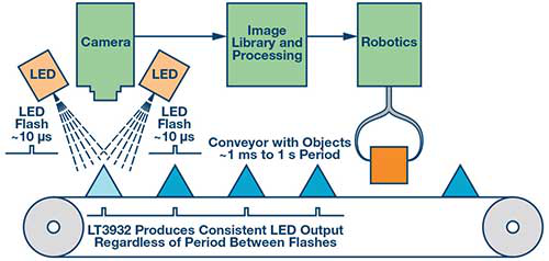
Figure 3. An example of machine vision on an industrial conveyor belt. The detection system moves at many different speeds, but the flash technology must be fast and clear.

Figure 4. Two DC2286A LT3932 demonstration circuits can be easily paralleled to create the 3 A to 4 A machine vision LED flash application shown in Figure 1.
Epilogue
Machine vision systems can use paralleled LED drivers to create the fast, square, high-current waveforms required for automated image processing. The LT3932 LED driver’s proprietary camera flash technology can be scaled to higher currents by paralleling converters. Using paralleled LT3932 converters, 3 A and higher microsecond pulses can be achieved even with longer turn-off times. The LED camera flash waveform remains square and jitter-free, no matter how long the off-time is between LED flashes.
The Links: https://www.slw-ele.com/ltm10c210.html”> LTM10C210 LM190E08-TLGD


