Content last revised on February 9, 2026
MDC100-12 Power Diode Module: Technical Analysis for High-Reliability Rectifier Applications
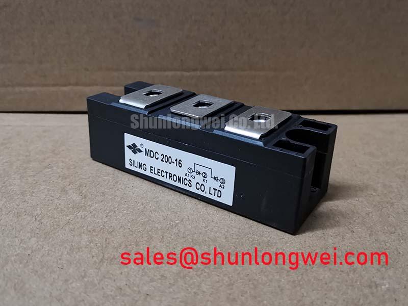
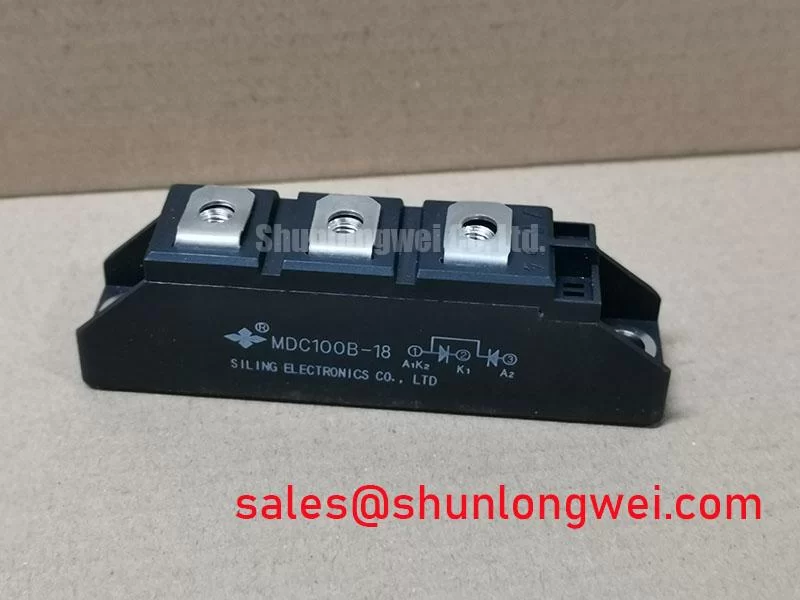
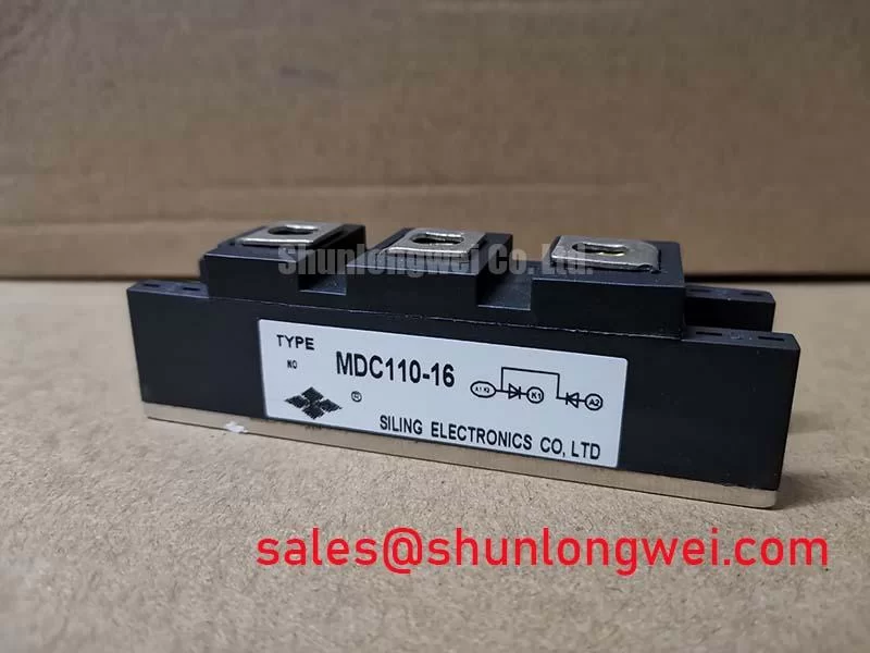
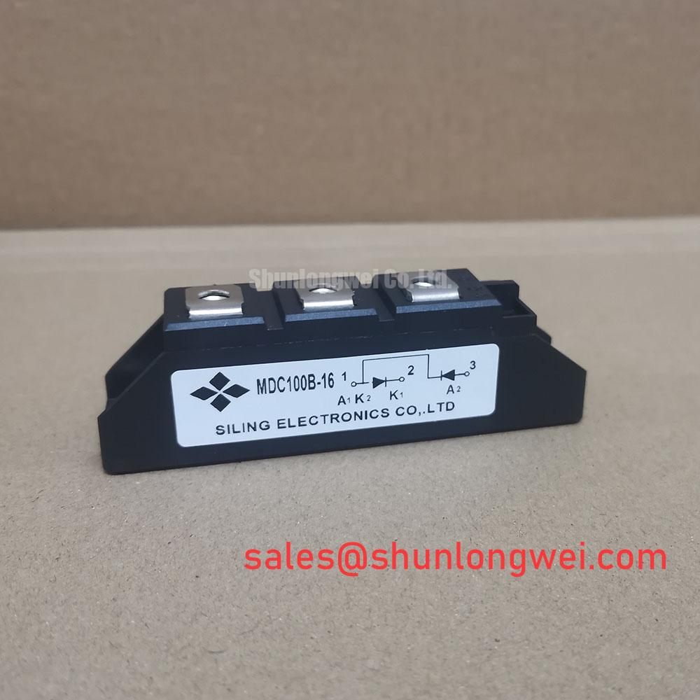
The MDC100-12 is a power diode module engineered for robust performance and superior thermal management in demanding industrial power conversion systems. With core specifications of 1200V | 100A | 2000A I(FSM), it provides a dependable foundation for rectifier circuits. Key benefits include enhanced system reliability under fault conditions and a simplified thermal design path. The module's high surge current rating ensures it can reliably handle the significant inrush currents typical in industrial battery chargers and motor start-ups. For uncontrolled rectifier stages in systems up to 100A requiring exceptional thermal and fault-current tolerance, the MDC100-12 is a premier design choice.
Application Scenarios & Value
Maximizing Uptime and Power Density in Industrial Rectifier Circuits
The MDC100-12 is engineered for high-stakes environments where reliability is non-negotiable. Its primary value is demonstrated in applications such as industrial-scale Battery Charging Systems and uninterruptible power supplies (UPS). Consider the challenge in a forklift charging station: the rectifier must not only provide a continuous high current but also withstand the severe inrush current when connecting a deeply discharged battery pack. The MDC100-12 directly addresses this with an impressive forward surge current (I(FSM)) rating of 2000A, preventing component failure and ensuring maximum charger uptime.
Furthermore, its excellent thermal performance, characterized by a low junction-to-case thermal resistance (Rth(j-c)) of 0.3 °C/W, is critical for power density. This efficiency in heat transfer allows engineers to implement more compact and cost-effective heatsink design strategies, or to operate at higher ambient temperatures without derating the current, a significant advantage in enclosed, non-ventilated power cabinets. For applications requiring operation on higher voltage lines or demanding greater safety margins, the related MDC100-16 provides a blocking voltage of 1600V.
Key Parameter Overview
Core Specifications for Thermal and Electrical Design
The performance of the MDC100-12 is defined by a set of critical electrical and thermal parameters that inform system design and ensure operational reliability. Below is a summary of its key specifications, directly sourced from the official datasheet.
| Parameter | Symbol | Condition | Value |
|---|---|---|---|
| Repetitive Peak Reverse Voltage | V(RRM) | - | 1200 V |
| Average Forward Current | I(F(AV)) | Tc = 85°C | 100 A |
| Peak Forward Surge Current | I(FSM) | t=10ms (50Hz), sine wave | 2000 A |
| I²t for Fusing | I²t | t=10ms (50Hz), sine wave | 20000 A²s |
| Peak Forward Voltage | V(FM) | I(FM) = 300A, Tj = 25°C | 1.70 V |
| Thermal Resistance, Junction to Case | Rth(j-c) | Per module | 0.3 °C/W |
| Isolation Voltage | V(iso) | a.c. 50HZ; r.m.s.; 1min | 2500 V |
| Operating Junction Temperature | T(vj) | - | -40 to 150 °C |
Interpreting the Specs:
- V(RRM) of 1200V: This represents the maximum repetitive reverse voltage the diode can block, providing a crucial safety margin for rectifiers connected to 380V or 480V three-phase AC lines. It acts like a pressure relief valve, defining the module's voltage handling limit.
- I(FSM) of 2000A: This parameter defines the module's robustness against massive, non-repetitive current surges. Think of it as the system's electrical airbag; it's a critical survivability metric that protects against catastrophic failure during events like motor startup or downstream short circuits, directly contributing to a longer operational life for the end equipment.
Technical Deep Dive
A Closer Look at the Module's Construction for Enhanced Operational Lifespan
The long-term reliability of a power module like the MDC100-12 extends beyond its primary electrical ratings. The internal construction plays a pivotal role, particularly in managing the stresses of thermal cycling. This module utilizes an industry-standard package with an electrically isolated mounting base, rated for 2500V AC. This design choice simplifies assembly by allowing multiple modules to be mounted on a single, non-isolated heatsink, reducing parts count and potential assembly errors.
The core of this reliability is the direct-bonded substrate technology that joins the semiconductor die to the baseplate. This substrate serves a dual purpose: it provides the high dielectric strength for electrical isolation while simultaneously acting as an efficient thermal conduit. This construction minimizes the thermal stress experienced by the silicon during repeated power-up and power-down cycles. It's analogous to the expansion joints in a bridge; it absorbs the stress from repeated heating and cooling, preventing the formation of micro-cracks and ensuring the module's integrity over thousands of operational hours. This inherent robustness is fundamental to achieving a low total cost of ownership in industrial systems where maintenance and downtime are significant cost drivers.
Frequently Asked Questions
Engineering Questions on the MDC100-12
What is the primary advantage of the MDC100-12's thermal resistance specification?
The low thermal resistance of 0.3 °C/W per module allows for highly efficient heat transfer from the silicon junction to the heatsink. This directly enables more compact system designs with smaller heatsinks, or alternatively, provides greater thermal margin for enhanced reliability in high-temperature operating environments.
How does the 1200V V(RRM) rating of the MDC100-12 influence its suitability for different AC line voltages?
The 1200V rating provides a substantial safety margin for building rectifier bridges connected to global industrial AC lines, including 380V, 400V, and 480V systems. This high blocking voltage capability ensures the device can safely withstand the peak voltages and transients common in these industrial electrical grids.
In a practical application like a welding power supply, how does the surge current (I(FSM)) rating protect the system?
In a Welding Power Supply, the MDC100-12's high I(FSM) of 2000A is critical for surviving the demanding current pulses and potential short-circuit conditions inherent to welding processes. This robustness prevents diode failure, protecting the downstream inverter stage and ensuring the welder's operational longevity in harsh conditions.
What are the key considerations for mounting and heatsinking the MDC100-12 module for optimal performance?
For optimal thermal performance, the module's baseplate must be mounted to a flat, clean heatsink surface using a thin, uniform layer of thermal interface material. Applying the correct mounting torque to the terminals is crucial to ensure low Thermal Resistance and prevent mechanical stress on the module's housing.
The strategic selection of the MDC100-12 enables the design of power conversion systems that are not only electrically proficient but also thermally robust and reliable over the long term. Its specifications are tailored to mitigate the common failure points in industrial rectifiers—thermal stress and surge currents—making it a sound engineering choice for building resilient power infrastructure.