
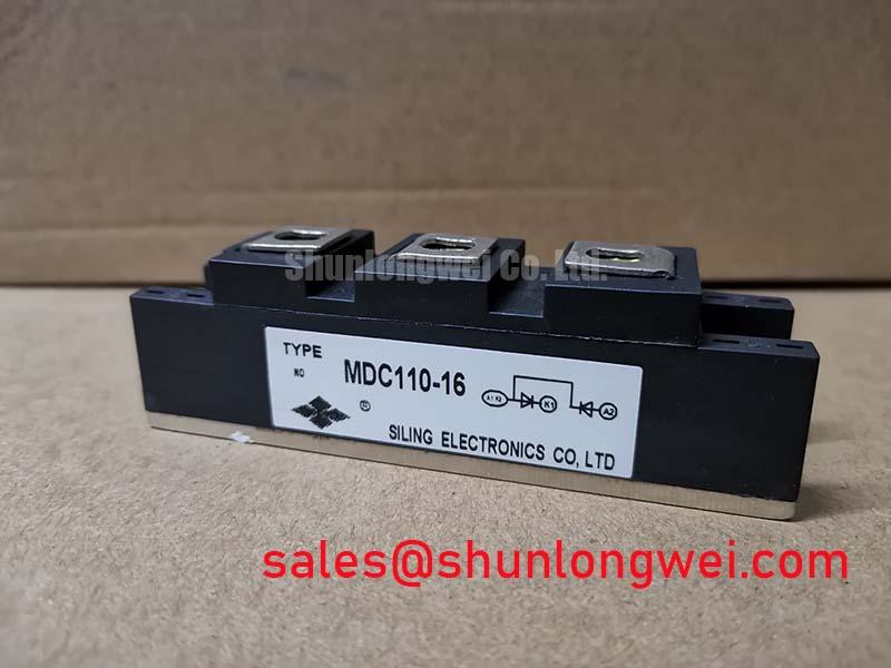



Content last revised on September 30, 2026
MDC100-16 Surge Checks During Benchtop Repair
| Model | Manufacturer | Product category | Package |
|---|---|---|---|
| MDC100-16 | IXYS | Dual diode module | SOT-227B / TO-240AA |
Measure each diode path in both directions with the equipment isolated, then compare the readings with a known-good assembly before investigating a reported surge failure. A continuity result alone cannot establish whether the MDC100-16 remains suitable for service: inspect terminal connections, the mounting surface and the heatsink contact area as part of the same repair check.
For fuse coordination, obtain the module’s specified surge-current and I²t limits, including their pulse duration and starting-temperature conditions, from the applicable IXYS documentation. Compare those conditions with the protective fuse’s clearing I²t at the prospective fault current. A surge rating for a single event should not be treated as permission for repeated motor-start transients. Check the module’s thermal condition between events and the reverse voltage that reappears afterward; those measurements determine whether the installed circuit stays within its documented limits.
Use the specified mounting procedure and torque for the actual hardware rather than transferring a value from another SOT-227B assembly. During preventive maintenance, clear dust from the heatsink airflow path, inspect the condition of the thermal interface and check terminal tightness using the equipment maintenance procedure. Maintenance note: Isolate and discharge the circuit before loosening a module terminal or disturbing its heatsink mounting.
Rectifier Waveforms in a Motor Soft-Starter Assembly
Probe the AC input and rectified output while checking a soft-starter assembly for uneven conduction; correlate any missing or distorted interval with the wiring diagram and the individual diode paths. The MDC100-16 is a dual diode module, so it has no gate terminal and cannot set a firing angle. A changing firing angle belongs to a separately controlled thyristor stage, not to this module.
In a system that includes phase control, compare the measured input-current waveform with the commanded thyristor firing sequence before attributing poor power factor or reactive-current demand to the rectifier. The diode module’s role depends on how its terminals are connected in the complete circuit. Verify that terminal mapping against the equipment schematic and the applicable module drawing before fitting a replacement.
If the circuit also contains a complementary rectifier stage such as the RM150UZ-2H, assess each device against its own connection diagram and ratings. The MDC300-16 is another model to compare during parts evaluation, but its name does not establish electrical, thermal or mounting interchangeability with the MDC100-16.
MDC100-16 Operating Boundaries and Adjacent Gate Circuits
Trace the suspected gate-drive signal to its controlled switch, not to the MDC100-16, when a firing pulse appears absent or unstable. Gate trigger current, pulse rise time and holding current are thyristor concerns; assigning them to a dual diode module would send troubleshooting toward the wrong terminals. If the equipment uses thyristors or IGBTs nearby, check their drive waveforms against their respective device specifications while evaluating the diode module separately for polarity, current path and temperature rise.
As a Design Consideration, keep drive and power-loop wiring arranged to limit parasitic coupling, then confirm the result from measured switching waveforms under the equipment’s operating conditions. The Evolution of Negative Off-Bias Gate Drive Circuits provides context for evaluating an adjacent controlled-switch drive; negative gate bias is not an operating requirement of the MDC100-16. Where a fast-switching stage shares a current path with a diode, recovery behavior can affect observed transients. ROHM’s fast recovery diode information and the explanation of the reverse recovery effect describe that mechanism, without establishing a recovery rating for this module.
MDC100-16 Circuit Protection and Maintenance Checks
Capture the voltage across the installed diode path during a reported line disturbance, and compare the peak with the module limit specified for the relevant conditions. If an input MOV or RC snubber is present, inspect its connections and assess its measured behavior with the complete circuit in view. MOV selection and snubber values are system design decisions: the line environment, switching waveforms and protective-device ratings must be checked together rather than inferred from the module package.
For a prospective short circuit, coordinate the semiconductor fuse’s clearing I²t with the module’s documented withstand conditions and the available fault current. Do not substitute a generic fuse table for the actual fuse curve or assume a surge rating covers an indefinite fault. After a protective trip, record diode-path readings and terminal condition before re-energizing; a trip does not identify a single failed component by itself.
As a Design Consideration for a high-voltage three-phase motor solid-state soft starter, assess condensation exposure and cabinet airflow alongside electrical protection. During scheduled inspection, look for moisture at terminals, dust restricting heatsink airflow and changes in contact temperature. Resolve those observations against the enclosure design and maintenance records before returning the assembly to duty.