


Content last revised on September 28, 2026
TDB6HK95N16LOF Thermal-Electrical Optimization: AC Line Surge Immunity and Practical Tuning
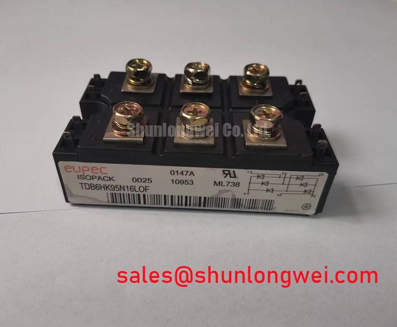
Verify the nameplate against the approved bill of materials, then inspect the Infineon TDB6HK95N16LOF for terminal damage, baseplate distortion, contamination, and loose mounting hardware before connecting it to a live circuit. The supplied factory data identifies this device as a PowerBlock Module with a 1600.0 V rated voltage and a 200.0 A rated current. These values establish the product identity and electrical boundary; they do not replace the complete manufacturer datasheet for surge, thermal, gate, fuse, or transient specifications.
For evaluation in a high-voltage three-phase motor solid-state soft starter, the first engineering task is to confirm the complete protection chain around the thyristor or diode stage. The 1600.0 V rating should be compared with the actual line-to-line voltage, transient exposure, commutation conditions, and the selected isolation and protection architecture. The supplied product information does not specify an IEEE 61000-4-5 surge withstand level, so system-level surge compliance must be tested rather than inferred from the voltage rating.
MOV selection, line fusing, and RC snubber placement should be treated as coordinated design work. Designers should verify the MOV working voltage, clamping behavior, pulse energy, and failure mode against the equipment transient environment. Fuse coordination also requires the manufacturer’s approved I²t data and the prospective fault current of the installation. Those values are not included in the supplied factory parameter set and should not be substituted with a generic table.
Terminal connections deserve the same attention as semiconductor ratings. Confirm conductor preparation, phase identification, clearance, and tightening requirements from the applicable Infineon mechanical documentation. During commissioning, capture the line voltage and current waveform at controlled load conditions, then compare abnormal overshoot or ringing with the known-good phase path. The Infineon EconoDUAL™ 3 reference material provides useful industry context for power-module integration, but it is not a substitute for the TDB6HK95N16LOF datasheet.
Benchtop Waveform Tuning: Junction-to-Heatsink Heat Dissipation
On the bench, begin with a clean, flat heatsink interface and inspect the module baseplate before applying thermal compound. The supplied data confirms the PowerBlock Module package, but it does not provide the thermal resistance, permitted case temperature, mounting torque, or thermal cycling limits. Those parameters must be obtained from the correct manufacturer documentation before calculating heat dissipation or approving a heatsink assembly.
A practical thermal check should record the temperature rise at comparable load points across all phases. Uneven temperature behavior may indicate nonuniform contact pressure, an unsuitable thermal interface, blocked airflow, terminal resistance, or an electrical imbalance. Verify the heatsink surface, fastener sequence, compound coverage, and fan or duct condition as one assembly. Do not use a torque value copied from another PowerBlock variant unless the mechanical document confirms that it applies to this exact device.
Maintenance Note: Isolate power before inspection, periodically remove dust from the heatsink and airflow path, and monitor contact temperature during scheduled load tests.
TDB6HK95N16LOF Thermal-Electrical Optimization: ITSM Assessment Across Repetitive Mains Events
The supplied factory parameters do not state the non-repetitive surge current ITSM, its sinusoidal test duration, junction-temperature condition, or recovery requirement before reverse voltage is reapplied. For that reason, a repair engineer should not derive a surge-current limit from the 200.0 A rated current. The continuous rating and short-duration surge rating describe different operating conditions and require separate verification.
When a soft starter experiences repeated starts, stalled acceleration, phase imbalance, or rapid restart commands, review the recorded current waveform and thermal trend together. Check whether the control system allows adequate cooling between events and whether the semiconductor stage is exposed to reverse voltage before the junction temperature has returned to an acceptable condition. The exact safe operating window remains system-determined until the official ITSM, thermal impedance, and transient specifications are confirmed.
Gate triggering also requires documentary verification. IGT, VGT, gate pulse width, repetitive pulse capability, and gate-cathode protection values are not provided in the supplied data. A pulse-train approach may be evaluated by the designer, but the final trigger circuit must be validated against the original gate characteristics and the isolated driver. Infineon’s EiceDRIVER™ galvanically isolated gate-driver information offers relevant driver-system background without establishing specifications for this module.
TDB6HK95N16LOF Operational Boundaries: Critical Rate of Rise of Off-State Voltage
Rapid off-state voltage transitions can interact with stray capacitance, wiring inductance, snubber behavior, and gate-control layout. The critical dv/dt limit for the TDB6HK95N16LOF is not included in the supplied parameter list, so engineers should obtain the official value before setting an RC snubber or approving a high-speed switching test.
The design principle is to control transient voltage rise and unwanted current concentration while preserving the intended soft-starter waveform. RC networks, series reactors, and line-side suppression should be selected from measured voltage and current traces, component pulse ratings, fault conditions, and thermal results. System engineers should verify peak voltage margins against the installation voltage during controlled switching tests rather than treating a generic snubber value as a product requirement.
For cross-reference work, the TD210N12 may be reviewed as a separate device for objective electrical and mechanical comparison; compatibility must be established from its own documentation. In the upstream power path, the TT570N16 can be assessed as a separate rectifier or complementary-stage option where the system topology requires it. Long-term thermal review, protection coordination, and switching verification can be expanded through the Power Electronics Masterclass, while final acceptance should remain tied to the applicable Infineon technical documents and measured equipment results.