




Content last revised on September 29, 2026
Assembly Integrity and Layout Architecture for 2MBI200U4H-120
| Specification | Official Value |
|---|---|
| Manufacturer | Fuji Electric |
| Model | 2MBI200U4H-120 |
| Product category | IGBT Module |
| Rated voltage | 1200 V |
| Rated current | 200 A |
| Package | Fuji Power Module |
Probe the gate drive, emitter reference, and collector to emitter waveform with an oscilloscope when a forklift traction inverter shows intermittent overvoltage faults or unexplained switching shutdowns. Compare the measured turn off transient with the known good phase leg while checking the DC link voltage at the same time. This separates a device level switching concern from a supply disturbance, gate loop problem, or measurement error.
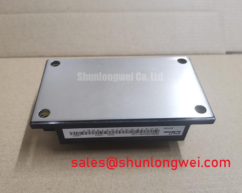
The 2MBI200U4H-120 is a 1200 V, 200 A Fuji Electric IGBT module in a Fuji Power Module package. Those are official product specifications, not recommended operating points for a complete inverter. Actual current, switching frequency, junction temperature, pulse duration, and cooling conditions must be evaluated against the original Fuji Electric technical documentation and the finished equipment design.
For a hard switching bridge, the commutation loop should be physically compact, with the positive and negative DC bus conductors arranged to reduce opposing current loop area. Laminated busbar construction can help reduce parasitic inductance, but the final result depends on conductor geometry, insulation spacing, fastener arrangement, and the position of the local DC link capacitors. During commissioning, observe the collector emitter voltage directly at the power terminals using a suitable differential probe. Long probe ground leads can create ringing that is not present in the power circuit.
Short circuit protection requires a coordinated detection and turn off strategy. A system designer may evaluate a fast desaturation or overcurrent detection path, blanking behavior, gate clamping, and a controlled two stage soft turn off sequence. The appropriate response time and gate current are system determined because the available short circuit withstand capability, stray inductance, gate driver behavior, and DC link conditions must be verified for the selected module and application. Do not treat a generic protection delay as an official rating for this model.
When a fault appears only after the module reaches operating temperature, inspect the gate resistor connections, driver supply stability, thermal interface condition, and busbar fasteners before replacing the power module. A phase leg that switches differently from its companion leg should be checked for unequal gate loop length and emitter return routing. Engineers evaluating related Fuji power modules may also compare the available 2MBI50-120, while confirming voltage, current, mechanical, and electrical compatibility independently.
Operational Boundaries and Common Mode Bearing Current Evaluation
Capture the motor terminal waveform at the inverter output and again at the motor when long cable runs produce bearing current alarms, motor insulation stress, or unexpected common mode noise. Compare the edge shape, ringing frequency, and peak voltage at both locations rather than diagnosing the IGBT module from the motor symptom alone. Cable impedance, termination conditions, motor construction, grounding, and switching behavior can combine to produce reflected wave effects.
A long motor lead behaves as a transmission line at sufficiently fast voltage transitions. Reflected energy can raise the motor terminal peak above the local inverter waveform, and severe cases can approach twice the incident voltage under specific termination conditions. This is a general power drive design consideration, not an official electrical rating or guaranteed behavior of the 2MBI200U4H-120. The system engineer should verify the motor terminal peak against the motor insulation requirement and measure the module voltage separately during switching tests.
Output reactors, dv/dt filters, common mode chokes, and shield termination methods should be selected from measured cable length, motor data, switching conditions, leakage current limits, and thermal performance. A filter that reduces the motor edge rate can also change driver losses, control response, and common mode current. Select the network as part of the complete traction inverter rather than assigning a universal filter value to this IGBT module.
High side gate power integrity deserves the same attention. Where an isolated or bootstrap driver is used, the gate supply reservoir should be assessed from total gate charge, driver quiescent current, switching frequency, leakage paths, refresh time, and allowable gate voltage ripple. The required capacitance is therefore a system calculation, not a fixed specification of the power module. Confirm that the driver can maintain the intended gate bias during the complete high side conduction interval.
Use a short, controlled gate return path and keep power commutation conductors separated from sensitive control wiring. If the measured gate voltage contains repeated disturbances synchronized with the collector waveform, inspect Miller coupling, driver grounding, gate resistance, and the probe reference arrangement. The external reference Fuji Electric 7th Gen X Series IGBT Modules provides broader manufacturer context for power semiconductor technology, but it should not be used to infer unlisted specifications for this exact model.
Braking Resistor and Chopper Transient Coordination
Measure the DC link voltage during the actual deceleration event and inspect the chopper gate waveform when a forklift drive reports overvoltage trips during braking. Record the bus voltage before, during, and after the event while checking the braking command, resistor temperature, contactor state, and regenerative load. This confirms whether the energy path is functioning before the chopper module is considered defective.
The braking circuit must absorb the kinetic and electrical energy returned by the motor without exceeding the voltage and thermal limits of the complete drive. The resistor value, pulse rating, duty cycle, cooling method, and switching strategy are determined by vehicle mass, speed, deceleration profile, DC link capacitance, battery behavior, and the control system. These values cannot be assigned from the 1200 V and 200 A nameplate ratings alone.
During design review, distinguish the continuous resistor rating from its short duration pulse capability. A resistor can survive a brief event yet overheat during repeated pallet handling cycles or frequent direction changes. Thermal sensors, airflow checks, and event logging are useful for identifying accumulated heat that is not visible during a single bench test. If the braking resistor is external, verify its insulation clearance, cable routing, enclosure temperature, and connection torque as part of the equipment inspection.
The chopper loop should be arranged to limit stray inductance between the switching device, DC link capacitor, and braking resistor connection. Excessive loop inductance can produce turn off overshoot and ringing, while poorly routed gate wiring can create false turn on or nuisance protection events. Engineers should verify the peak collector emitter voltage at the module terminals during the worst expected braking pulse, including a low battery condition and a fully charged battery condition where applicable.
Repeated braking faults also justify an inspection of the energy management control. A battery charger, bidirectional DC DC converter, or regenerative front end can alter the DC link response and increase thermal cycling in the power stage. The broader converter topology can be reviewed through Peak Efficiency in Solar and Energy Storage, while the final braking network must be validated against the forklift drive topology and measured operating profile.
Derating and Mismatched Parameter Guidelines for 2MBI200U4H-120
Compare the collector current, gate voltage, switching waveform, and case temperature between parallel or phase matched power paths when one leg runs hotter or produces a different fault signature. Check the thermal interface, mounting pressure, busbar symmetry, gate resistor placement, and emitter return path before attributing the imbalance to semiconductor variation.
The official identification for this product is a 200 A rated current and 1200 V rated voltage Fuji Electric IGBT module. These figures define the product category and rated boundaries, but they do not establish a permissible current at every switching frequency, coolant temperature, pulse duration, or overload condition. The system designer should apply the manufacturer’s curves and test the complete assembly under its real electrical and thermal duty.
IGBT forward voltage generally has a positive temperature coefficient in operating regions used for static current sharing, which can support balanced conduction between appropriately matched devices. Dynamic sharing is more sensitive to gate loop inductance, driver timing, stray capacitance, busbar symmetry, and unequal thermal paths. Parallel operation should therefore be treated as an engineering recommendation requiring waveform comparison and temperature measurement, not as an automatic consequence of using modules with the same printed rating.
For a bidirectional DC DC battery system, map the charge and discharge current paths separately. Battery state of charge, regenerative events, ambient temperature, coolant condition, and switching duty can create different thermal cycles in each direction. Preventive maintenance should track the trend of terminal temperature and heat sink temperature under repeatable load conditions rather than relying only on an instantaneous current reading.
⚠️ Maintenance Note: De energize the drive before terminal work, then inspect heat sink cleanliness, thermal interface aging, busbar fasteners, and enclosure condensation control during scheduled service.
When a field unit shows abnormal heating, verify the heat sink contact pattern and airflow path, then compare its phase waveform with a known good phase. A rise in contact temperature may involve degraded thermal material, blocked airflow, loose mounting hardware, excessive switching loss, or a control mismatch. Record the measurement conditions so that replacement evaluation is based on comparable evidence rather than a single temperature value.