



Content last revised on September 28, 2026
6MBP30RTA060 Thermal Interface and Electrical Ratings
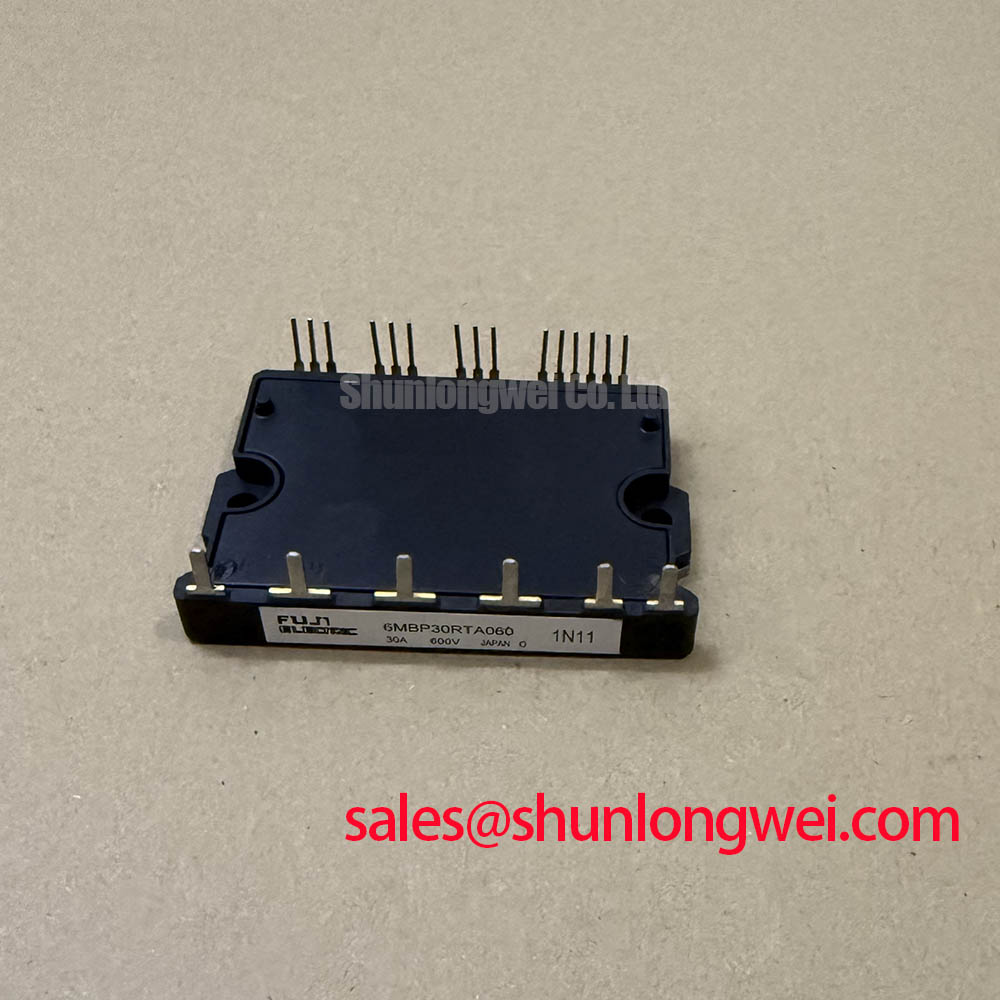
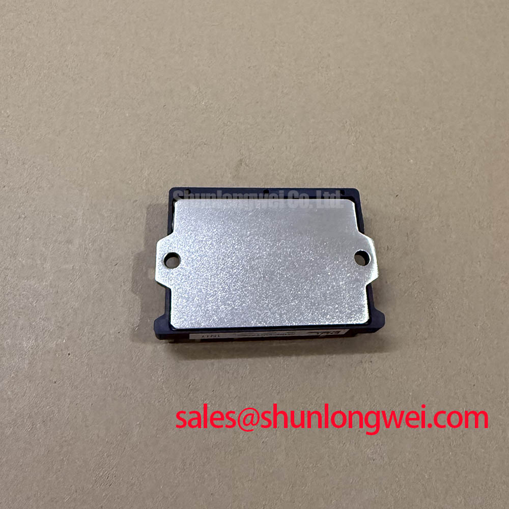
With the DC link isolated and discharged, check the module markings against the repair record, then inspect the heatsink contact surface before mounting the 6MBP30RTA060. Fuji Electric specifies this IPM at 600 V collector to emitter and 30 A collector current (Official Datasheet Specifications). Its 7-in-1 configuration combines a three-phase converter, a three-phase inverter and a brake function (Official Datasheet Specification). Match that complete arrangement to the equipment schematic; voltage and current ratings alone do not establish fit.
For thermal interface work, the aim is a continuous, thin layer of grease without trapped air or heavy ridges (Design Consideration). Clean the mating surfaces, inspect them for damage and apply the material according to the heatsink and interface-material instructions. A visibly uneven imprint after a trial fit may warrant checking heatsink flatness and mounting alignment. It does not, by itself, identify a defect inside the module. Tighten mounting fasteners progressively in the sequence and to the torque specified for the actual assembly rather than assigning a generic torque to this part.
Fuji Electric lists a typical 1.7 V collector-emitter saturation voltage at 30 A (Official Datasheet Specification). That test-point value is useful when reviewing conduction loss, but it is not a measured loss figure for every operating temperature or drive condition. Designers should evaluate the equipment’s switching duty, cooling path and available thermal data before deciding whether a repaired drive has adequate junction-temperature margin. Where transient thermal impedance data are available from the applicable documentation, compare pulse heating with the full duty cycle rather than treating a steady-state heatsink reading as the peak junction temperature.
Maintenance Note: Recheck heatsink airflow and contact temperature during scheduled service, particularly after cleaning or thermal-interface replacement.
Field Diagnostics and Gate-Drive Isolation
Before commissioning, trace the control connector and protection signals against the machine schematic. The 6MBP30RTA060 specifies over-current, short-circuit, under-voltage and over-temperature protection (Official Datasheet Specifications). Confirm how the host controller receives and responds to a protection indication; the presence of an internal protection function does not establish the shutdown behavior of the complete drive. If a fault persists, compare the control supply, command and fault waveforms with a known-good operating state where one is available.
The specified module isolation test is 2500 V AC for 1 minute (Official Datasheet Specification). It must not be restated as a rating for a reinforced gate-drive barrier or as a common-mode transient immunity rating. Those are separate properties of the surrounding drive circuitry and require their own component documentation and system assessment (Design Consideration). Fuji Electric’s power semiconductor and IPM information provides manufacturer context; the equipment documentation remains necessary for connector assignments and commissioning limits.
When investigating an apparent unintended turn-on, capture the command and relevant drive waveforms with appropriately rated measurement equipment. Check whether the disturbance coincides with switching elsewhere in the power stage, then inspect the control return path, connector seating and drive supply behavior. A bootstrap supply, if present in the host design, should be assessed against its driver consumption, switching activity and required hold-up interval; the module specifications supplied here do not establish a bootstrap capacitance or even require a particular external drive architecture.
Handle disconnected control assemblies using the workshop’s ESD procedures. The distinction between common electrostatic-discharge test models is background for handling practice, not an ESD withstand rating for this IPM. In humid or changing-temperature environments, inspect the enclosure for condensation paths before energizing the repaired equipment (Design Consideration).
Benchtop Switching Waveforms and Turn-Off Stress
Record the DC-link voltage and switching waveform under the equipment manufacturer’s approved test conditions before changing the power layout or protection circuit. At turn-off, current changing through stray inductance can add an overshoot to the DC-link voltage; the resulting peak must be assessed against the module’s 600 V collector-emitter rating (Official Datasheet Specification). The permitted operating margin, probe arrangement and test load belong to the system design and cannot be inferred from that rating alone.
If overshoot is observed, first check whether the measurement loop is introducing an apparent spike. Then examine the installed bus connections, DC-link capacitor connections and return-current path. Reducing unnecessary power-loop area is a Design Consideration for limiting inductive overshoot, but a target inductance cannot be assigned without the equipment layout and switching measurements. Snubber or clamp changes likewise need verification for peak voltage, component heating and behavior across the intended operating range; an unmeasured capacitor change can shift stress rather than resolve it.
A short-circuit investigation needs a separate check of the equipment’s semiconductor fuse and protection coordination. Compare the fuse maker’s clearing and let-through data with the available fault current and the module protection behavior, using the applicable time-current conditions. Neither a fuse rating nor the IPM’s stated short-circuit protection, taken alone, proves that a hard fault will be interrupted without damage. Record what the controller reported, inspect the power path and test the associated protective components before returning the drive to service.
For broader discussion of three-phase conversion and switching-device choices, The 1200 V CoolSiC MOSFET Advantage in Three-Phase Power Conversion is a separate technology reference. Its device ratings and behavior should not be transferred to the 6MBP30RTA060.
Assembly Integrity and Braking-Circuit Compatibility
Identify the braking terminals on the equipment drawing before reconnecting the motor and DC link. The 7-in-1 converter, inverter and brake configuration is an Official Datasheet Specification for the 6MBP30RTA060, but it does not specify an external braking resistor value or a complete deceleration duty. The resistor and any external braking components must be evaluated against the machine’s stored mechanical energy, deceleration pattern, DC-link behavior and their own thermal ratings (Design Consideration). Observe the resistor maker’s mounting and clearance instructions, especially where heat could affect nearby wiring.
During a controlled commissioning run, review the DC-link response during deceleration and check for protection events or abnormal resistor heating. If the link voltage rises unexpectedly, consider the commanded ramp, braking path continuity, resistor condition and measurement setup before assigning a cause. A compact industrial inverter or high-speed CNC spindle drive may be a candidate application, subject to confirmation of its electrical connections, control interface, cooling arrangement and braking duty.
For replacement evaluation, compare terminal layout, converter and inverter arrangement, brake function, protections and mechanical fit against the original equipment documentation. The 6MBI100L-060 is another Fuji Electric module that may appear in a parts review, but its designation must not be treated as evidence of direct interchangeability with this IPM. After assembly, retain the mounting and waveform observations in the maintenance record so a later change in cooling contact, terminal condition or deceleration behavior can be assessed against the repaired unit’s commissioning state.