Content last revised on April 15, 2026
VBO13-08NO2: Robust 800V Single-Phase Rectifier Bridge for Industrial Power Conversion
Introduction and Key Features
Engineered for High-Reliability AC/DC Rectification
The IXYS VBO13-08NO2 is a single-phase rectifier bridge engineered for robust performance in demanding industrial power applications. It combines high voltage and current ratings within a compact, high-isolation package, providing a dependable foundation for power supply and drive designs. With core specifications of 800V | 13A | 3600V~ Isolation, this module delivers enhanced electrical safety and excellent thermal performance. Its design directly addresses the need for reliable line-frequency rectification in equipment operating from standard 230V and 400V AC lines. For space-constrained power supplies requiring high electrical isolation and long-term operational stability, the VBO13-08NO2 offers an optimal rectification solution.
- What is the primary benefit of its high isolation voltage? It provides enhanced system safety and simplifies compliance with industrial standards.
- How does its construction enhance reliability? The use of planar passivated chips ensures stable and predictable performance over the component's lifetime.
Key Parameter Overview
Decoding the Electrical and Thermal Specifications for Robust Design
The technical specifications of the VBO13-08NO2 are tailored for reliable performance in industrial environments. The parameters below highlight its capacity for handling significant electrical and thermal loads, forming the basis for sound engineering design decisions.
| Parameter | Symbol | Value | Condition |
|---|---|---|---|
| Absolute Maximum Ratings | |||
| Repetitive Peak Reverse Voltage | VRRM | 800 V | |
| Average Forward Current | IdAV | 13 A | TC = 135°C, resistive load |
| RMS Forward Current | IFRMS | 30 A | |
| Peak Forward Surge Current | IFSM | 170 A | t = 10 ms, TVJ = 45°C |
| I2t Value for Fusing | I2t | 145 A2s | t = 10 ms, TVJ = 45°C |
| Electrical Characteristics | |||
| Forward Voltage Drop (per diode) | VF | < 1.6 V | IF = 45 A, TVJ = 25°C |
| Reverse Current (per diode) | IR | < 0.2 mA | VR = VRRM, TVJ = 25°C |
| Thermal and Mechanical Characteristics | |||
| Operating Junction Temperature | TVJ | -40°C to +150°C | |
| Storage Temperature | Tstg | -40°C to +150°C | |
| Thermal Resistance, Junction to Case | RthJC | 2.4 K/W | Per diode |
| Isolation Test Voltage | VISOL | 3600 V~ | 50/60 Hz, RMS, t = 1 min |
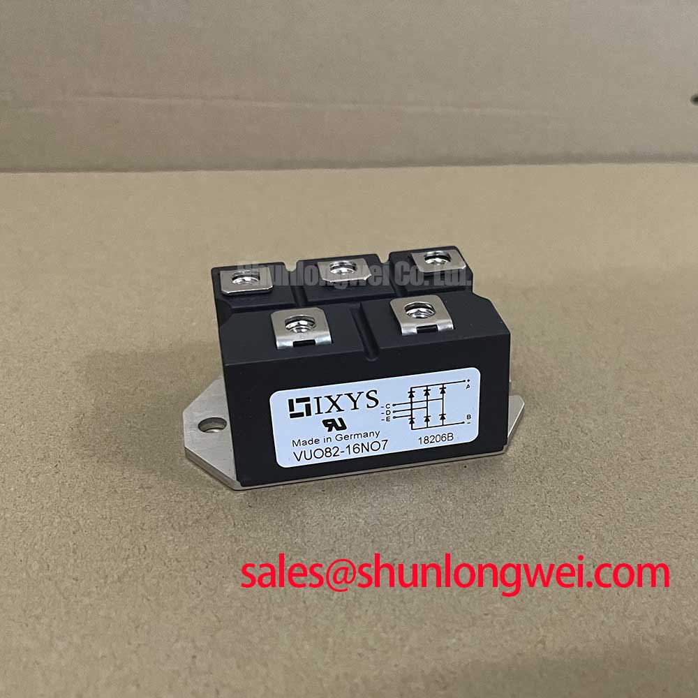
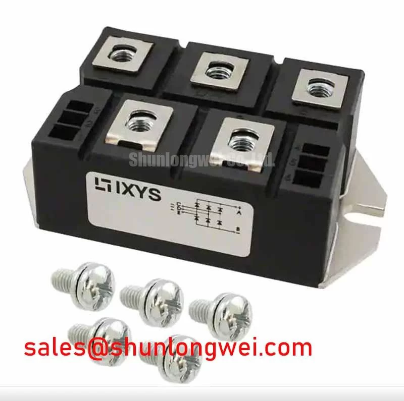
| Package | - | TO-240 AA | |
Download the VBO13-08NO2 datasheet for detailed specifications and performance curves.
Application Scenarios & Value
System-Level Reliability in Power Supplies and DC Motor Control
The VBO13-08NO2 is engineered for applications where robust and efficient AC-to-DC conversion is a prerequisite for system reliability. Its characteristics make it a strong candidate for the front-end rectification stage in a variety of industrial equipment.
High-Fidelity Engineering Scenario: Industrial Battery Charger Design
In the design of a power stage for an industrial battery charger, engineers face the dual challenge of ensuring operator safety while managing heat in a compact enclosure. The VBO13-08NO2's 3600V~ isolation voltage is a critical feature. This high dielectric strength provides a substantial safety margin, simplifying the design process for meeting stringent industrial safety standards like `IEC 60950`. This parameter acts like a robust electrical barrier, protecting downstream components and users from potential line faults. Furthermore, its relatively low thermal resistance (RthJC) allows for efficient heat transfer to a heatsink. This facilitates a more compact thermal design, crucial for reducing the overall size and cost of the charger's enclosure and `heatsink selection` process.
- Industrial Power Supplies: Provides reliable input rectification for switched-mode power supplies (SMPS) used in automation and control systems.
- DC Motor Drives: Serves as a dependable rectifier for small to medium-sized DC motor controls and field exciters.
- Battery Charging Systems: Forms the core of the AC input stage for chargers used in forklifts, golf carts, and backup power systems.
- General Purpose Rectification: Suitable for any application requiring the conversion of single-phase AC to DC power where reliability is paramount.
For systems that require significantly higher current handling capabilities for larger motor drives or high-power rectifiers, the related MDD95-12N1B offers current ratings up to 95A in a different module format.
Frequently Asked Questions
Engineering Questions on the VBO13-08NO2
What is the significance of the 3600 V~ electrical isolation for the VBO13-08NO2?
The 3600 V~ isolation rating is a measure of the dielectric strength between the electrical terminals and the mounting baseplate. For an engineer, this high value provides a significant safety margin, ensuring robust separation of the high-voltage AC input from the chassis ground. It simplifies meeting safety agency requirements (e.g., UL, CE) and enhances overall system safety, particularly in environments where voltage transients or line faults are a concern.
How do the planar passivated chips contribute to the reliability of the VBO13-08NO2 rectifier?
Planar passivation is a semiconductor manufacturing process that creates a stable, non-conductive layer (typically silicon dioxide or silicon nitride) over the silicon die's junctions. This layer protects the sensitive junction areas from environmental contaminants and electrical field effects. The result is a device with very low and stable reverse leakage currents, higher voltage blocking stability, and improved long-term reliability compared to non-passivated or less robust chip designs.
Technical Deep Dive
Analyzing the Impact of DBC and Chip Technology on Long-Term Performance
The long-term reliability of a power module like the VBO13-08NO2 is not defined by a single parameter but by the synergy of its internal construction technologies. Two key elements are the planar passivated chips and the Direct Bonded Copper (DBC) substrate. The DBC substrate consists of a ceramic insulator (typically Alumina, Al₂O₃) to which copper layers are directly bonded without an adhesive layer. This construction provides the module's high electrical isolation of 3600V~. More importantly from a thermal perspective, it creates a very efficient and robust path for heat to travel from the silicon chips to the module's baseplate and heatsink. This direct bond minimizes thermal fatigue points that can develop in modules using traditional soldered layers, leading to superior performance over thousands of thermal cycles—a common condition in applications like battery chargers or motor drives with start/stop operation.
Request for Technical Evaluation
To facilitate your design and evaluation process, we can provide detailed technical documentation. For further information or to discuss the integration of the VBO13-08NO2 into your specific application, please contact our technical support team for assistance.