

Content last revised on April 15, 2026
MG150J7KS50 Datasheet, Specs & Analysis: A 600V/150A High-Speed IGBT Module
Introduction to the MG150J7KS50 IGBT Module
A Strategic Component for High-Frequency Power Conversion
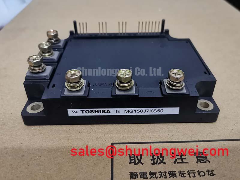
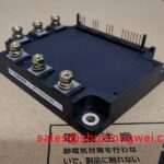
The Toshiba MG150J7KS50 is a 600V N-Channel Insulated Gate Bipolar Transistor (IGBT) Module engineered for high-speed power conversion, leveraging its fast switching characteristics to minimize losses and enhance power density. With core specifications of 600V | 150A | VCE(sat) of 2.7V (typ.), this module delivers two primary engineering benefits: significantly reduced switching losses and simplified thermal management through its isolated base. It directly addresses the need for efficiency in applications requiring rapid switching, such as industrial motor control and power supplies. For industrial VFDs and power supplies operating at higher PWM frequencies, the MG150J7KS50 offers a robust balance of speed and power handling.
Key Parameter Overview
A Data-Centric Look at Electrical and Thermal Performance
The technical specifications of the MG150J7KS50 provide a clear view of its capabilities. The parameters below are critical for system-level design, thermal modeling, and performance evaluation. Key values related to voltage handling, current capacity, and switching speed are highlighted to facilitate rapid assessment.
| Parameter | Symbol | Conditions | Value |
|---|---|---|---|
| Collector-Emitter Voltage | VCES | VGE = 0V | 600V |
| Gate-Emitter Voltage | VGES | ±20V | |
| Collector Current (DC) | IC | Tc = 25°C | 150A |
| Collector Current (1ms Pulse) | ICP | Tc = 25°C | 300A |
| Collector Power Dissipation | PC | Tc = 25°C | 625W |
| Collector-Emitter Saturation Voltage | VCE(sat) | IC = 150A, VGE = 15V | 2.7V (Typ.) / 3.3V (Max) |
| Turn-On Time | ton | IC = 150A | 0.30 µs (Typ.) |
| Turn-Off Time | toff | IC = 150A | 0.60 µs (Typ.) |
| Diode Reverse Recovery Time | trr | IF = 150A | 0.15 µs (Typ.) |
| Thermal Resistance (Junction to Case, IGBT) | Rth(j-c) | 0.2 °C/W | |
| Isolation Voltage | VISOL | AC, 1 minute | 2500V |
Download the MG150J7KS50 datasheet for detailed specifications and performance curves.
Application Scenarios & Value
System-Level Benefits in High-Speed Switching Applications
The MG150J7KS50 is optimally suited for power systems where switching speed is a critical design parameter. Its primary value proposition lies in enabling higher operational frequencies, which translates directly into smaller, lighter, and often more cost-effective system designs.
High-Fidelity Engineering Scenario: Consider an engineer designing a 50kW Variable Frequency Drive (VFD) for industrial automation. A key challenge is minimizing the physical size of the drive to fit into a constrained cabinet space. By utilizing the MG150J7KS50's fast turn-on (0.30 µs) and turn-off (0.60 µs) times, the engineer can confidently increase the Pulse Width Modulation (PWM) frequency. This action directly reduces the magnitude of ripple currents in the motor windings, allowing for the use of smaller, less expensive output filters and DC link capacitors. What is the main benefit of fast switching? It enables higher frequency operation, leading to smaller passive components.
- Industrial Motor Drives: The half-bridge configuration is the fundamental building block for three-phase inverters, making this module ideal for AC induction and permanent magnet motor controls.
- Welding Power Supplies: In high-frequency inverter-based welders, fast switching is essential for precise energy delivery and achieving a stable arc. The module's robust current handling (300A peak) manages the demanding pulses required.
- Switching Mode Power Supplies (SMPS): For high-power SMPS and UPS (Uninterruptible Power Supply) systems, the module's efficiency at higher frequencies helps reduce heatsink requirements and improve overall power density.
For systems that require operation at higher bus voltages, designers might evaluate components like the SKM150GB12V, which offers a 1200V rating.
Technical Deep Dive
Analyzing Switching Dynamics for Optimal Gate Drive Design
The performance of any IGBT module is intrinsically linked to its switching behavior. For the MG150J7KS50, the datasheet values for `ton`, `toff`, and `trr` are not just numbers; they are critical indicators of the device's efficiency. Switching losses, which occur during the transition between the on and off states, are a major source of heat. The total switching energy loss is directly proportional to the switching frequency. By minimizing the duration of these transitions, the MG150J7KS50 curtails energy waste, a crucial factor in high-frequency designs.
Think of switching losses as the small amount of energy wasted every time you flip a sticky, slow-moving light switch. A faster, crisper switch (representing lower `ton` and `toff`) wastes less energy with each flip. When this action occurs thousands of times per second in a PWM scheme, these small savings accumulate into a significant reduction in waste heat. Furthermore, the rapid reverse recovery time (`trr` = 0.15 µs) of the integrated free-wheeling diode is paramount. A slow diode can cause significant losses and voltage stress on the opposing IGBT in the half-bridge. The fast `trr` of the MG150J7KS50's diode acts like a valve that shuts off instantly without significant backflow. This prevents a momentary shoot-through current, a major source of inefficiency and potential device failure, making the module more reliable in hard-switching topologies. A well-designed gate drive circuit is essential to fully realize these speed advantages.
Frequently Asked Questions (FAQ)
How do the switching times of the MG150J7KS50 influence the choice of operating frequency in an SMPS design?
The fast switching times (ton ≈ 0.30 µs, toff ≈ 0.60 µs) directly reduce switching losses (Eon/Eoff). This lower heat generation per cycle allows designers to increase the PWM frequency, leading to smaller magnetic components and capacitors without excessive thermal stress, thereby improving the power density of the SMPS.
What is the significance of the 2.7V typical VCE(sat) rating for thermal calculations?
The VCE(sat) is the on-state voltage drop across the IGBT. It is the primary determinant of conduction losses (Pcond = VCE(sat) x IC). A lower VCE(sat) means less power is dissipated as heat during the 'on' phase of a cycle. While 2.7V is a moderate value, it is crucial for calculating the total power dissipation and subsequently selecting an appropriately sized heatsink to maintain the junction temperature within its safe operating area.
What are the primary considerations for designing a gate drive circuit for this module?
To achieve the specified high switching speeds, the gate drive circuit must have low output impedance to quickly charge and discharge the IGBT's input capacitance. A recommended gate voltage of +15V for turn-on and a negative voltage (e.g., -5V to -15V) for turn-off is advisable to ensure a fast, clean turn-off and prevent parasitic turn-on due to dV/dt effects.
Is the isolated mounting base sufficient for all applications, or is additional insulation required?
The module features an isolation voltage rating of 2500V (AC for 1 minute), which is sufficient for most industrial applications operating on standard bus voltages (e.g., up to 400V). The integrated isolation simplifies assembly by eliminating the need for separate thermal pads like mica, which can have inconsistent thermal performance. However, system-level insulation requirements should always be verified against the relevant safety standards (e.g., IEC 61800-5).
Strategic Outlook
Integrating the MG150J7KS50 allows design teams to push performance boundaries in established industrial systems. Its focus on switching speed provides a strategic pathway to creating more compact, efficient, and cost-effective power conversion solutions. This aligns with persistent industry trends toward higher power density and improved energy efficiency, ensuring that designs based on this module remain competitive and compliant with evolving performance expectations in the power electronics landscape.