


Content last revised on June 21, 2026
Toshiba MG25Q2YS40: A Deep Dive into this 1200V Half-Bridge IGBT Module
Introduction: Core Specifications and Engineering Value
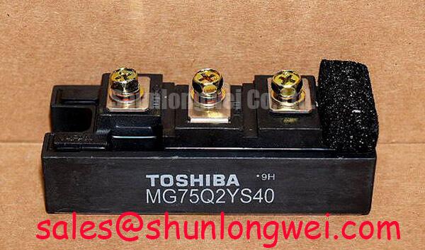
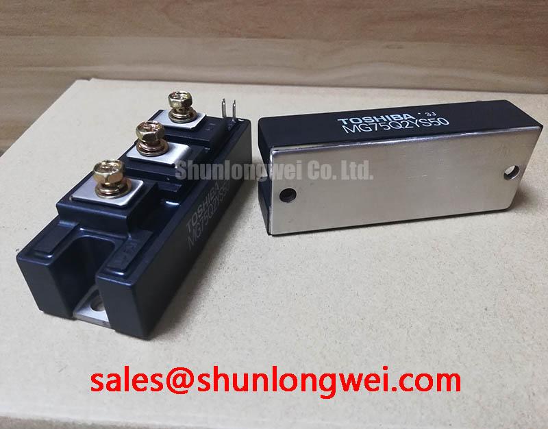
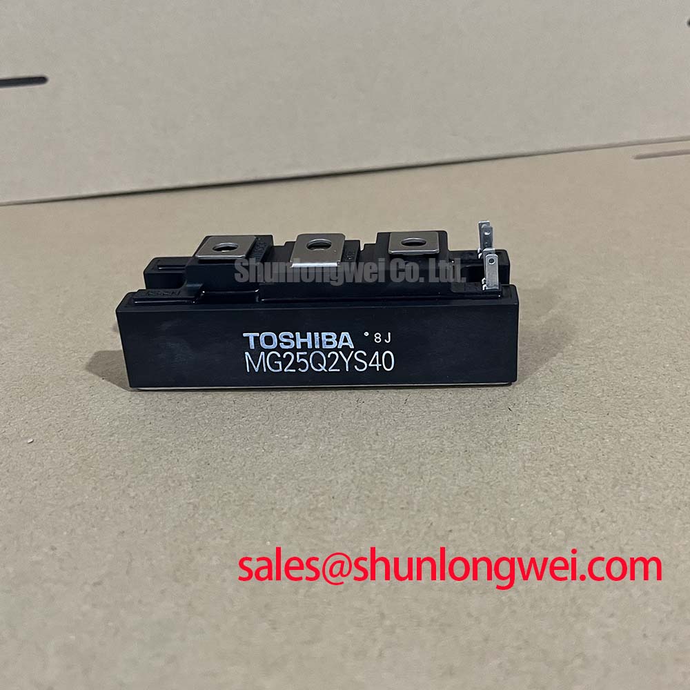
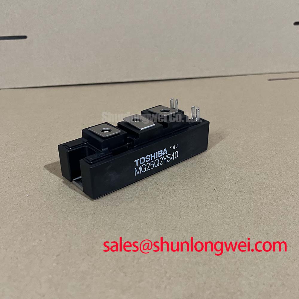
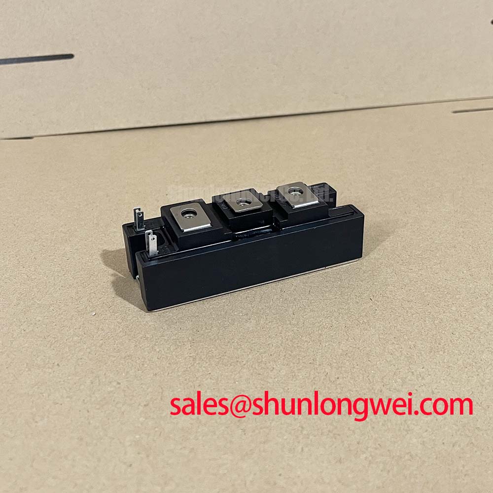
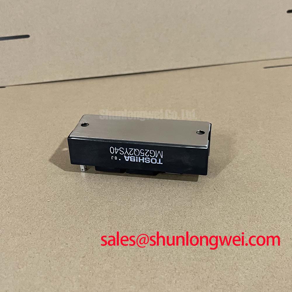
Engineered for robust performance in demanding power conversion systems, the Toshiba MG25Q2YS40 is a GTR Module featuring two Silicon N-Channel IGBTs in a half-bridge configuration. It delivers a formidable combination of high-voltage resilience and moderate current handling, defined by its core specifications: 1200V | 25A | VCE(sat) 4.0V (Max). This module provides the essential benefits of high input impedance for simplified gate drive design and an integrated package that reduces system complexity. It directly addresses the need for reliable switching components in industrial motor controls and power supplies. For systems requiring higher current capabilities, the related MG150Q2YS50 offers a similar voltage rating with enhanced amperage.
Key Parameter Overview
Decoding the Specs for Reliable Power Switching
The technical specifications of the MG25Q2YS40 are foundational to its performance in high-power applications. The parameters outlined below are critical for circuit design, thermal management, and ensuring the module operates within its safe operating area. Each value represents a commitment to performance under specified conditions, directly influencing system efficiency and long-term reliability.
| Parameter | Symbol | Conditions | Min | Typ | Max | Unit |
|---|---|---|---|---|---|---|
| Collector-Emitter Voltage | VCES | VGE = 0V | - | - | 1200 | V |
| Gate-Emitter Voltage | VGES | VCE = 0V | - | - | ±20 | V |
| Collector Current (DC) | IC | - | - | - | 25 | A |
| Collector Current (Pulse) | ICP | - | - | - | 50 | A |
| Collector Power Dissipation (per IGBT) | PC | Tc = 25°C | - | - | 250 | W |
| Collector-Emitter Saturation Voltage | VCE(sat) | IC = 25A, VGE = 15V | - | 3.0 | 4.0 | V |
| Fall Time | tf | IC = 25A | - | 0.3 | 0.5 | µs |
| Reverse Recovery Time | trr | IF = 25A | - | 0.2 | 0.5 | µs |
| Operating Junction Temperature | Tj | - | -40 | - | 150 | °C |
Download the MG25Q2YS40 datasheet for detailed specifications and performance curves.
Application Scenarios & Value
System-Level Benefits in Industrial Drives and Power Systems
The MG25Q2YS40 IGBT module is best suited for applications where reliability and efficient power switching are paramount. Its 1200V rating provides substantial voltage headroom for systems operating on 400V or 480V AC lines, making it a strong candidate for industrial machinery. What is the primary benefit of its integrated half-bridge design? It simplifies the power stage layout, reducing stray inductance and improving reliability compared to using discrete components. In a Variable Frequency Drive (VFD), for instance, this module can serve as the core of the inverter stage, controlling the speed of a three-phase AC motor. The specified maximum fall time (tf) of 0.5µs is crucial here; it directly impacts switching losses, which in turn dictate the required heatsink size and overall VFD efficiency. A faster fall time means less time is spent in the high-dissipation linear region, translating to cooler operation and a more compact end product.
Technical Deep Dive
Analyzing Switching Characteristics and Saturation Voltage
Two key parameters that define the operational effectiveness of the MG25Q2YS40 are its switching speed and on-state voltage drop. The combination of a typical fall time (tf) of 0.3µs and a reverse recovery time (trr) of 0.2µs allows for efficient operation in switching applications up to the lower kilohertz range, typical for motor control. Think of the switching process like a water faucet: the faster you can turn it completely on or off, the less water (or energy) is wasted during the transition. The module's VCE(sat) of 4.0V (max) at the rated 25A collector current is a critical factor for conduction loss. This value represents the residual voltage across the device when fully turned on. A lower VCE(sat) is analogous to a wider pipe, allowing current to flow with less resistance and, consequently, generating less heat. For designers, this means predictable thermal performance and reduced energy waste during the motor's run cycle.
Industry Insights & Strategic Advantage
Meeting the Demands for Robust Industrial Automation
In the landscape of industrial automation and power control, the trend toward more integrated and reliable components is clear. The MG25Q2YS40, by consolidating a half-bridge circuit into a single, isolated package, aligns with this industry demand. This design approach inherently enhances system robustness by minimizing connection points and simplifying assembly, crucial factors in high-vibration environments like CNC machines or conveyor systems. The 1200V breakdown voltage provides the necessary safety margin required by standards governing industrial equipment, ensuring resilience against voltage transients common on factory floors. As manufacturers push for higher uptime and lower maintenance costs, components like the MG25Q2YS40 that offer a straightforward path to a dependable power stage become a strategic asset in system design.
Frequently Asked Questions (FAQ)
What does the half-bridge configuration of the MG25Q2YS40 simplify in a power circuit?
The integrated half-bridge (two IGBTs in series) simplifies the layout of inverter and chopper circuits. It reduces the number of components, minimizes parasitic inductance by shortening connection paths, and streamlines the assembly process, leading to a more compact and reliable power stage.
How does the 4.0V maximum VCE(sat) impact thermal design?
The VCE(sat) directly determines the conduction losses (P = VCE(sat) * IC). A specified maximum of 4.0V at 25A allows engineers to calculate the worst-case heat generation during the on-state. This is a critical input for selecting an appropriately sized heatsink to maintain the junction temperature below the 150°C maximum, ensuring long-term operational stability.
Is the MG25Q2YS40 suitable for high-frequency applications?
With a maximum fall time of 0.5μs and reverse recovery time of 0.5μs, this module is well-suited for low-to-medium frequency applications such as motor drives and welding power supplies, typically operating in the range of a few kHz up to 20 kHz. For applications requiring significantly higher switching frequencies, designers would need to carefully evaluate the trade-off with increased switching losses.
What is the significance of the isolated case design?
The electrodes being electrically isolated from the mounting case simplifies thermal management. It allows the module to be mounted directly to a common heatsink without the need for additional insulating pads, which would otherwise add thermal resistance. This improves heat transfer efficiency and simplifies the mechanical design of the overall system.
Engineering Perspective
From an engineering standpoint, the MG25Q2YS40 is a pragmatic choice for power applications where proven technology and reliability are prioritized over cutting-edge switching speeds. Its specifications are well-matched for the demands of industrial motor control, small uninterruptible power supplies (UPS), and other power conversion tasks. The value lies in its integration and straightforward application, offering a robust building block that allows design teams to focus on system-level performance rather than the intricacies of discrete component layout and matching.