

Content last revised on September 24, 2026
CM150DY 12NFA Circuit Protection and Reliability: DC Bus Layout Review
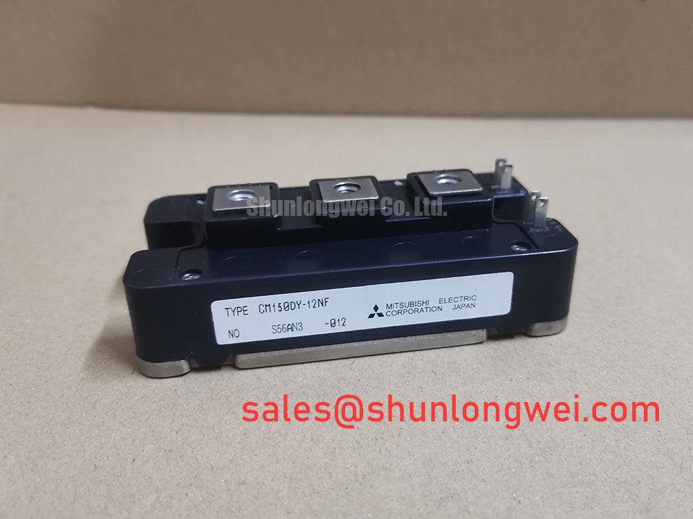
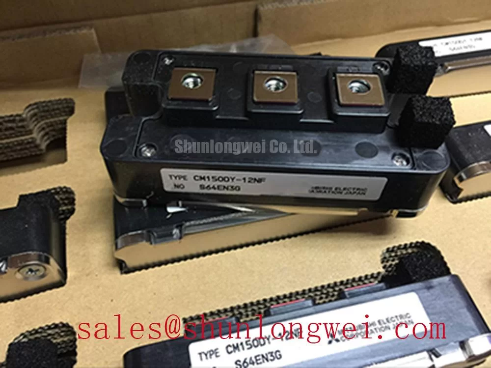
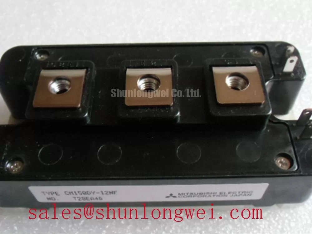
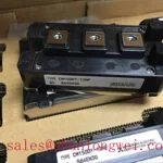
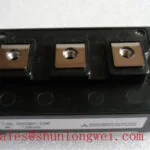
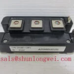
Before fitting the CM150DY 12NFA, isolate the drive, confirm the module marking, and compare the existing power terminal arrangement with the original equipment documentation before any busbar or gate wiring is removed. This Mitsubishi Electric IGBT module is officially rated at 600.0 V and 150.0 A, with a Module package. These are Official Datasheet Specifications and establish the electrical identity that maintenance teams should verify when assessing a replacement for a heavy duty variable frequency AC motor drive.
| Parameter | Specification |
|---|---|
| Product model | CM150DY 12NFA |
| Manufacturer | Mitsubishi Electric |
| Rated voltage | 600.0 V Official Datasheet Specification |
| Rated current | 150.0 A Official Datasheet Specification |
| Package | Module Official Datasheet Specification |
CM150DY 12NFA Circuit Protection and Reliability: DC Bus Layout Review
For a replacement installation, inspect the DC busbar faces, capacitor connections, insulation barriers, and fastening hardware before placing the CM150DY 12NFA into service. A laminated busbar arrangement is commonly evaluated in high current inverter assemblies because closely coupled positive and negative conductors can reduce the commutation loop area. This is a Design Consideration, not a module specific factory requirement.
During turn off, peak device voltage is influenced by the DC link voltage plus the voltage generated by stray inductance and current change rate. In practical commissioning, the system engineer should measure collector emitter switching waveforms at the installed gate drive condition and verify that observed voltage peaks remain within the system design limits. A snubber network, where used, should be assessed together with DC link capacitor placement, busbar geometry, switching frequency, cable routing, and the actual motor load.
Do not assume that a replacement module resolves a repetitive overvoltage event. Inspect for loosened capacitor terminals, distorted copper busbars, damaged insulating films, contamination between conductive surfaces, and evidence of thermal discoloration around connection points. A phase controlled input rectifier can also affect DC link ripple and harmonic content, so the complete drive input and capacitor bank should be reviewed when an inverter shows recurring protection trips.
For teams comparing current capacity across related Mitsubishi Electric module families, the CM300DXDX1 24A can be reviewed as a separate reference part. Mechanical dimensions, terminal layout, voltage class, gate drive requirements, thermal path, and control board compatibility must be checked against the original equipment documentation before any substitution assessment.
⚠️ Maintenance Note: Periodically inspect contact temperature rise and confirm that cooling air passages remain clear before returning a high current drive to sustained duty.
CM150DY 12NFA Operational Boundaries: Voltage, Altitude, and Installation Review
The 600.0 V official voltage rating should be treated as a module boundary rather than as a complete inverter operating prescription. DC bus conditions depend on the supply arrangement, regenerative events, braking circuit behavior, capacitor condition, motor cable effects, switching transients, and protection response. When integrating or repairing a drive, designers should verify the original DC bus operating range and measured switching margin under the actual machine cycle.
Altitude, humidity, condensation exposure, contamination, and enclosure ventilation are system level conditions. No specific failures in time value, terrestrial neutron failure rate, single event burnout rate, altitude derating value, or lifetime prediction is stated here because those results require a validated manufacturer source and application specific operating data. At elevated installation locations, the system integrator should review enclosure insulation coordination, clearance distances, cooling performance, and the applicable equipment safety requirements.
Before energization, compare the original module terminal designations with the drive schematic and inspect creepage and clearance paths around the busbar and gate connector area. Vibration resistant fastening should be evaluated using the equipment manufacturer’s specified hardware and service procedure. A busbar that appears secure at rest can still shift under vibration or thermal cycling, affecting contact resistance and insulation spacing.
Mitsubishi Electric maintains technical context for its power semiconductors and high power modules. For service work, the original drive documentation remains the controlling source for terminal assignment, protection thresholds, mounting arrangement, and approved commissioning checks.
CM150DY 12NFA Operational Boundaries: Symmetrical Busbar Geometry for High Current Paths
Current sharing in a multi device power stage depends on more than the nominal current marking. Equal path resistance, similar power loop inductance, matched gate drive routing, consistent heatsink contact, and comparable thermal conditions all influence how parallel paths behave during switching and continuous operation. This is a Design Consideration for the inverter assembly and should not be interpreted as an internal construction claim for the CM150DY 12NFA.
Where an inverter topology uses parallel power paths, engineers should keep corresponding busbar routes geometrically comparable and avoid one path having an unnecessarily long return route or a remote DC link capacitor connection. The gate loop should also be reviewed for unequal routing, shared return impedance, connector damage, or changes made during previous repairs. Oscilloscope measurements compared with a known good phase can help identify a waveform imbalance that may warrant layout or driver investigation.
At the heatsink interface, remove old thermal material carefully and inspect the mounting plane for debris, corrosion, scratches, or local distortion. Apply the thermal interface material in accordance with the equipment maker’s service instructions and use the specified tightening sequence. Uneven mounting pressure may raise thermal resistance at one area of the baseplate and can complicate interpretation of phase current or temperature related trips.
For maintenance programs concerned with thermal interfaces, airflow management, and evolving cooling approaches, The Advanced Thermal Management Revolution provides broader technical reading. The installed drive’s heatsink, fan condition, dust loading, and ambient environment still determine the service outcome for this specific module.
Preventing Spurious Faults: High Speed Fault Management and VCE Desaturation Review for CM150DY 12NFA
A desaturation protection circuit belongs to the gate driver and system protection architecture, not to the stated factory ratings of this IGBT module. Its purpose is generally to identify an abnormal rise in collector emitter voltage while the device is commanded on, then initiate a controlled protection response. The correct detection blanking, threshold behavior, gate discharge path, and restart logic must be verified from the original driver documentation.
In a motor drive repair, inspect the desaturation sensing diode, gate driver supply stability, driver ground return, isolation components, and the connector path between the control board and power module. A nuisance trip may be associated with switching noise, poor return routing, an unstable auxiliary supply, a damaged sensing path, or an actual power stage overload. It should be investigated through controlled measurements rather than attributed to a single cause.
Soft turn off behavior is often considered where a protection event must reduce gate drive without creating an excessive inductive voltage transient. This is an Engineering Recommendation for system level protection design. Its suitability depends on the measured power loop inductance, DC link condition, load current, gate driver behavior, and the fault energy capability defined by the original drive manufacturer.
When reviewing the wider power conversion assembly, a related CM100DY 12E may appear in associated converter or power stage documentation. It should be treated as a separate component reference, with its own ratings and application checks, rather than as a direct replacement for the CM150DY 12NFA.