


Content last revised on February 5, 2026
CM400DY1-12E: A Technical Guide to the 600V/400A Dual IGBT Module
Product Overview: Balancing Power and Efficiency
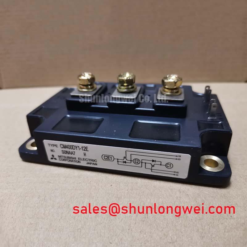
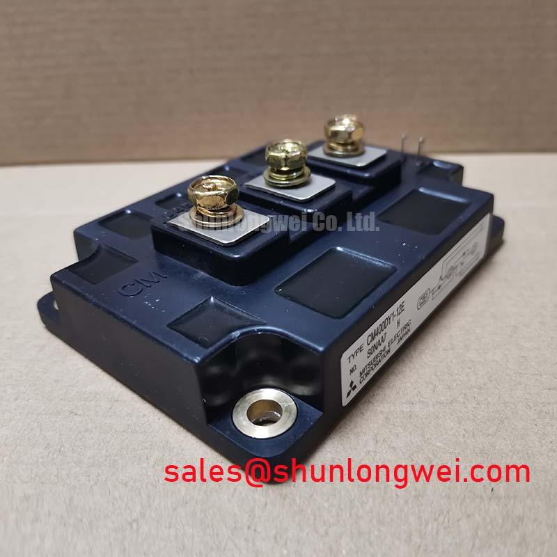
The Mitsubishi CM400DY1-12E is a high-current dual IGBT module engineered to deliver robust performance and high efficiency in demanding power conversion systems. This module provides a formidable combination of high current handling and low conduction losses, making it a cornerstone for powerful and reliable inverter designs. Key specifications include: 600V | 400A | VCE(sat) of 1.9V. Its primary engineering benefits are significantly reduced thermal dissipation and enhanced system efficiency. This component directly addresses the need for power stages that can manage substantial loads without compromising on thermal stability or performance. For industrial drives requiring precise control and high reliability, the CM400DY1-12E's low saturation voltage is a critical design advantage.
Application Scenarios & Value
System-Level Benefits in High-Current Motor Drives
The CM400DY1-12E is optimized for high-power, high-frequency applications where thermal management and efficiency are paramount. Its capabilities are particularly evident in the design of industrial Variable Frequency Drives (VFDs) and servo drives used to control large induction motors.
A primary engineering challenge in these systems is managing the heat generated during continuous, high-current operation. The module's collector-emitter saturation voltage (VCE(sat)) of just 1.9V at its nominal 400A rating directly confronts this issue. This low VCE(sat) minimizes conduction losses, which are the dominant source of power loss in high-current, steady-state conditions. For a system designer, this translates into a lower thermal load on the heatsink, enabling more compact mechanical designs or increasing the system's operational thermal margin for enhanced reliability. What is the main benefit of a low VCE(sat)? It directly reduces power loss as heat, leading to a cooler and more efficient system.
For applications demanding even greater current capacity, such as those found in heavy industry or traction, the related CM600DX-24T provides a higher current rating within a similar technological framework.
Key Parameter Overview
Highlighting Critical Performance Specifications
The technical specifications of the CM400DY1-12E are tailored for robust, high-efficiency power switching. The parameters below are essential for system design, thermal modeling, and performance validation.
| Parameter | Symbol | Conditions | Value |
|---|---|---|---|
| Collector-Emitter Voltage | VCES | VGE = 0V | 600 V |
| Collector Current (DC) | IC | TC = 100°C | 400 A |
| Collector-Emitter Saturation Voltage | VCE(sat) | IC = 400A, VGE = 15V | 1.9 V (Typ.) / 2.3V (Max.) |
| Total Power Dissipation | PC | TC = 25°C, per transistor | 2080 W |
| Thermal Resistance (Junction to Case) | Rth(j-c) | IGBT | 0.06 K/W |
| Operating Junction Temperature | Tj | - | -40 to +150 °C |
Note: These parameters represent key highlights. For comprehensive electrical and thermal characteristics, performance curves, and application notes, please refer to the official datasheet.
Technical Deep Dive
Balancing Conduction and Switching Performance
The core of the CM400DY1-12E's performance lies in its sophisticated trade-off between conduction losses and switching losses. The module utilizes an advanced trench gate CSTBT™ (Carrier Stored Trench-Gate Bipolar Transistor) structure. This technology is instrumental in achieving the low 1.9V typical VCE(sat) at a high current of 400A.
To understand its impact, consider an analogy: VCE(sat) is like the resistance of a fully open water valve. A lower resistance means less pressure (voltage) is lost and less energy is wasted as heat when water (current) flows through. By minimizing this "resistance," the CM400DY1-12E ensures that most of the energy is delivered to the load rather than being dissipated in the switch itself during on-state operation. While optimizing for low VCE(sat), the design also maintains controlled switching characteristics (Eon and Eoff), ensuring that the energy lost during the transitions from on-to-off and off-to-on is kept within manageable limits for typical industrial frequencies. This balance is critical for maximizing the overall efficiency of a power converter across its entire operating cycle.
Frequently Asked Questions (FAQ)
How does the VCE(sat) of 1.9V directly influence heatsink selection?
A lower VCE(sat) reduces the power dissipated as heat (P_loss = VCE(sat) * IC). With less heat to manage, engineers can often specify a smaller, more cost-effective heatsink or utilize the saved thermal budget to push the system to higher power outputs without exceeding the maximum junction temperature. This directly impacts overall system size, cost, and power density.
What is the primary advantage of the dual (2-in-1) configuration?
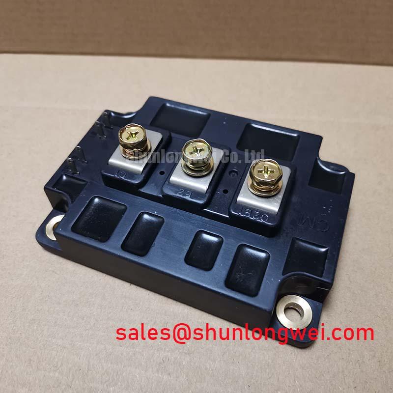
The dual configuration integrates two IGBTs, typically arranged as a half-bridge leg, into a single, compact module. This simplifies the mechanical layout of an inverter, reduces stray inductance between switches compared to discrete solutions, and streamlines the manufacturing process. It's a foundational building block for creating three-phase inverters by using three identical modules.
What are the key considerations for the gate drive circuit for this module?
For optimal performance, the gate drive circuit must be capable of providing sufficient peak current to charge and discharge the gate capacitance quickly, minimizing switching times. The recommended gate-emitter voltage (VGE) of +15V is critical to ensure the IGBT is fully saturated to achieve the low VCE(sat). A negative turn-off voltage (e.g., -5V to -10V) is also advisable to provide a strong defense against parasitic turn-on induced by dV/dt, enhancing noise immunity.
Is the CM400DY1-12E suitable for applications requiring high short-circuit robustness?
Yes, the datasheet specifies short-circuit withstand time (tsc), typically in the range of 10 microseconds under specific conditions. This capability allows the protection circuitry adequate time to detect a fault condition and safely shut down the gate drive before the IGBT suffers catastrophic failure, a crucial feature for ensuring the reliability of industrial power systems.
Strategic Application
For engineering teams developing next-generation power conversion platforms, the CM400DY1-12E represents a strategic component choice. Its integration facilitates the design of systems that not only meet today's power demands but also align with increasing market pressure for higher energy efficiency and smaller physical footprints. By building a power stage around a module with inherently low conduction losses, designers can gain a competitive advantage in system performance, reliability, and total cost of ownership for the end-user.