Content last revised on September 26, 2026
CM200DXD1-24A Benchtop Waveform Tuning and Voltage Stress
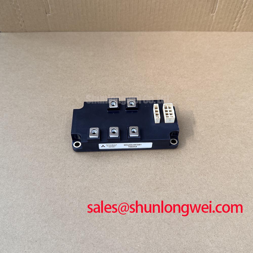
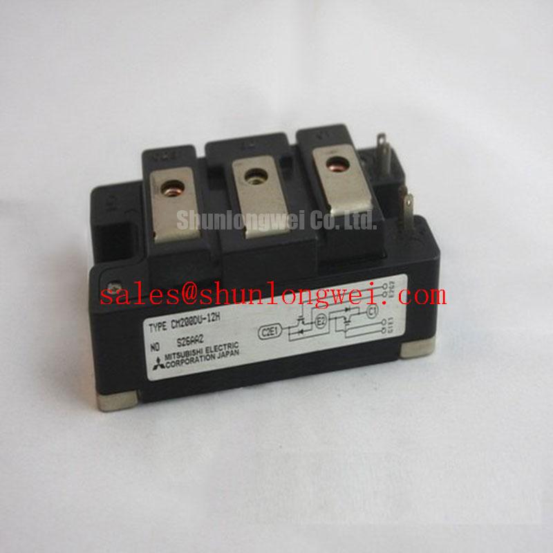
With the drive isolated and its DC link confirmed discharged, compare the module marking and mounting footprint with the unit removed from the equipment before measuring the gate and power terminals. The CM200DXD1-24A is a Mitsubishi Electric IGBT module with a stated 1200 V voltage rating and 200 A current rating (Official Specification). These ratings establish an initial identification boundary, not a complete interchangeability test: the original equipment documentation must also establish the terminal arrangement, gate-drive requirements and cooling interface.
Begin switching checks at the gate terminals and the DC-link connection, using measurement methods appropriate to the drive’s voltage and isolation requirements. A clean command at the controller does not establish a clean waveform at the module. Gate-loop inductance, shared return paths and the placement of drive components can alter the voltage actually seen at the gate during switching. As a Design Consideration, keep the gate-drive loop compact to limit ringing, then assess the resulting gate waveform and collector-emitter overshoot under representative operating conditions. Gate resistance and damping are system-determined choices; neither should be assigned from the module’s current rating alone.
Compare turn-on and turn-off captures with a known-good phase or an established service record when one exists. Look for repeated ringing, unexpected gate excursions and changes in overshoot as load current varies. An abnormal trace does not identify a failed module by itself. Probe placement, DC-link connections, drive-supply behavior and measurement bandwidth deserve checking before a component-level diagnosis. The acceptance decision should rest on measured switching peaks against the applicable module limits and the equipment’s operating conditions.
High-altitude reliability calls for a separate assessment rather than a calculated failure rate invented from the voltage rating. Terrestrial neutron exposure and single-event burnout are relevant Design Considerations for high-voltage semiconductor operation, but this product information provides no device-specific FIT or single-event-burnout data for CM200DXD1-24A. Where an installation requires quantified altitude or DC-bus derating, the equipment designer should obtain applicable manufacturer reliability information and evaluate the actual bus profile. Routine waveform testing remains useful for finding switching stress; it cannot measure a cosmic-ray failure rate.
CM200DXD1-24A Overcurrent Protection and Drive-Board Checks
Trace the protection path from current sensing or desaturation detection through the gate-driver shutdown command before enabling a repaired drive under load. Short-circuit protection depends on the module, driver, sensing method and total response path together. No device-specific short-circuit withstand time or SCSOA limit is established by the ratings stated here, so a fixed detection deadline should not be treated as an official CM200DXD1-24A specification. Verify protection timing and peak current against the original equipment design and the applicable manufacturer documentation.
A controlled turn-off can reduce inductive voltage overshoot during a fault, but the shutdown profile must still clear the fault within the verified protection boundary. Where a drive uses staged gate discharge, inspect the driver schematic and capture the gate and collector-emitter waveforms during a controlled validation test. A trip that appears only during rapid load changes may involve current-sense noise, gate coupling or an actual overcurrent event. Comparing the fault signal with the power-stage waveform helps distinguish these possibilities without treating any one symptom as a diagnosis.
On a high-side drive board, inspect the bootstrap supply under the switching pattern used by the machine. Repeated high-frequency charging, limited refresh time and diode recovery can affect the available gate-drive voltage; the required capacitor, diode and operating margin are system-determined. Check the isolated drive supply or bootstrap voltage at the driver during operation rather than relying only on a no-load bench reading. If the control board uses an optocoupler or digital isolator, review its common-mode transient immunity against measured switching conditions. An isolator specification is a board-level selection input, not a guaranteed immunity rating for this IGBT module.
At the power-stage level, distinguish the inverter switch from surrounding conversion and protection functions. The separately listed CM100DY-12E can be examined as a module in an equipment topology review, but its suitability for any rectifier or other position depends on that circuit’s schematic and verified ratings. Likewise, an RC snubber should be assessed against measured transients and its own dissipation; its values cannot be prescribed from the 1200 V rating alone.
Thermal Interface Inspection and Replacement Fit
Remove old interface material from the heatsink and inspect the mating surfaces before installing a module. Surface damage, trapped debris and uneven contact can undermine heat transfer even when the heatsink appears adequately sized. Apply the thermal interface material using the equipment or material supplier’s procedure, and examine the mounting pattern for evidence of uneven seating. Paste thickness and screw torque must follow the applicable assembly instructions rather than an assumed value for every module in a similar enclosure.
Maintenance note: Isolate the drive before opening the enclosure, and periodically check heatsink airflow and contact-temperature trends for changes that warrant inspection. Dust accumulation and aged thermal interface material deserve attention as part of planned maintenance, but a temperature change should prompt a check of airflow, load, sensing and mounting contact before assigning its cause. In humid or cold-start environments, assess condensation control at the enclosure level and allow the assembly to reach suitable operating conditions before energizing it.
Replacement assessment should start with the full mechanical drawing and circuit connections, not a higher current number. The CM300DXDX1-24A is another module to examine during a documented substitution review; its designation alone does not establish direct electrical or mechanical interchangeability with CM200DXD1-24A. Confirm the terminal map, mounting geometry, gate-drive compatibility, thermal path and protection settings against the original design before considering a change. For broader explanations of switching-loop and heatsink interactions, see IGBT Design & Integration. Mitsubishi Electric’s NX-Series IGBT Modules resource provides manufacturer context on module integration; it should not be read as a device-specific specification for this model.
DC-Link Overvoltage During Motor Deceleration
Capture DC-link voltage during a controlled deceleration if an overvoltage trip follows a drive repair. A motor returning energy to the inverter can raise the link voltage when the connected system cannot absorb that energy quickly enough. The CM200DXD1-24A voltage rating is an Official Specification, but it does not specify an allowable braking-energy budget. Compare the measured bus peak and switching overshoot with the equipment’s established limits before changing the deceleration command or braking hardware.
Some drives use a braking switch and resistor; their presence, connection and ratings must be confirmed from the actual schematic. Brake-switch current, resistor energy capacity, duty cycle and cooling are system-level design questions. Do not infer an internal braking IGBT from the module designation. If the trip persists, check the bus-voltage measurement path, braking command, resistor connections and load profile in sequence. For an electric forklift or warehouse traction-drive repair, that same compatibility review should include the original DC-bus arrangement and motor-control behavior rather than treating the application name as proof of fit.