Content last revised on October 7, 2026
Overvoltage Trip Prevention Through DC-Link Energy Management
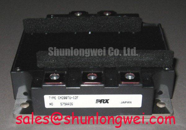
With the power supply isolated and the DC link verified discharged, compare the installed module’s terminal layout and nameplate with the replacement drawing before disconnecting CM200TU-12H. This Mitsubishi Electric IGBT module has an official rating of 600 V and 200 A. Those ratings establish two electrical boundaries; they do not, by themselves, confirm pin compatibility, gate-drive compatibility or thermal suitability in an industrial inverter welder or medium-frequency induction heating supply.
A DC-link overvoltage trip in a welder or induction heater calls for measurements before a module change. With appropriate high-voltage measurement equipment, compare the trip record with DC-link voltage during current interruption and power reduction. Check the bus capacitors, their connections and the equipment’s protection circuit against the original schematic. Repeated trips may reflect energy returning to the link, switching overshoot or a sensing problem; the symptom alone does not identify the IGBT as the cause.
Some drives use a braking chopper and resistor to dissipate deceleration energy. That arrangement should not be assumed present in a welder or heating supply, and CM200TU-12H should not be described as an internal braking IGBT without a confirmed circuit drawing. If the equipment does use a chopper, its switch, resistor and energy rating must be assessed as a separate subsystem. As a Design Consideration, verify conductor spacing and insulation against the equipment’s operating voltage, contamination conditions and applicable system requirements rather than applying an unverified clearance value to this module.
For repair evaluation, record the module’s mounted orientation, power-terminal connections and gate wiring before removal. A replacement decision should compare the original equipment documentation with the candidate module drawing and driver requirements, not just the 600 V and 200 A ratings.
Gate Impedance and Phase-Leg Dead-Time Verification
In a phase leg, rapid collector-voltage changes can couple into an IGBT gate and disturb the intended off state. An active Miller clamp or a negative gate supply can be evaluated as a Design Consideration where the existing driver supports it. Neither feature, nor a specific negative-bias setting, is established by the available CM200TU-12H rating information. Confirm the original driver schematic, gate-terminal arrangement and permitted gate-voltage limits before changing the drive circuit.
During controlled switching tests, observe both gate-to-emitter voltages and the phase-leg current around commutation. A brief unintended gate rise calls for examination of the driver return path, gate resistance, wiring symmetry and dead-time settings. Dead time must be checked under the equipment’s actual operating conditions: too little can permit cross-conduction, while too much can alter current behavior. Current-control methods such as deadbeat control also depend on the inverter’s real switching and sensing behavior; a control setting cannot establish the module’s electrical margin.
💡 Pro Tip: Keep the gate-drive return close to its corresponding gate path, then verify the resulting gate waveform during switching rather than assuming tidy wiring has suppressed ringing.
Switching-frequency or cooling changes require a fresh loss and temperature assessment. The 200 A official rating is not a promise that the module can carry that current continuously at every switching frequency or ambient temperature. As a Design Consideration, check measured case temperature, heatsink contact, airflow and the original equipment’s thermal limits under a representative duty cycle.
Busbar Geometry and Turn-Off Overshoot Measurement
Low-inductance, symmetrical DC-link connections can reduce turn-off overshoot, but no busbar-inductance target is established by the stated CM200TU-12H specifications. The relevant engineering relationship is that peak switch voltage rises with DC-link voltage and with the product of stray inductance and current slew rate. Accordingly, a bus layout that appears compact still needs measurement at the module terminals during representative switching.
Inspect busbar joints, capacitor connections and any fitted snubber for looseness, damage or deviation from the equipment drawing. Compare measured turn-off peaks with the module’s 600 V official voltage rating, accounting for measurement-probe placement and operating variation. If a snubber is being revised, its value and physical placement should be determined from the actual waveform, losses and circuit layout; a generic capacitor value cannot establish protection for this installation.
Keep power and gate-return paths distinct when documenting a repair. Before reassembly, verify mounting surfaces and fastener requirements from the module and equipment documentation. Uneven contact or an incorrect mounting method can complicate thermal diagnosis even when an electrical bench check appears normal.
Parallel-Module Current Sharing and Replacement Assessment
If an equipment assembly parallels modules, compare the individual current paths before assuming equal sharing. Busbar resistance, connection condition, cooling differences and gate-drive timing can all affect how current divides. A favorable temperature coefficient at one operating point should not be treated as a guarantee of static or dynamic balance across the full duty cycle without device characteristics and measurements.
As a Design Consideration, keep corresponding power paths and gate-drive connections symmetrical, then compare branch currents and switching waveforms under controlled load. A branch that runs hotter warrants checks of its electrical connections, drive waveform and heatsink interface before attributing the difference to the module alone. For test planning and failure-analysis methods, the Field Engineer’s Handbook provides broader engineering context; it does not establish a service-life figure for this model.
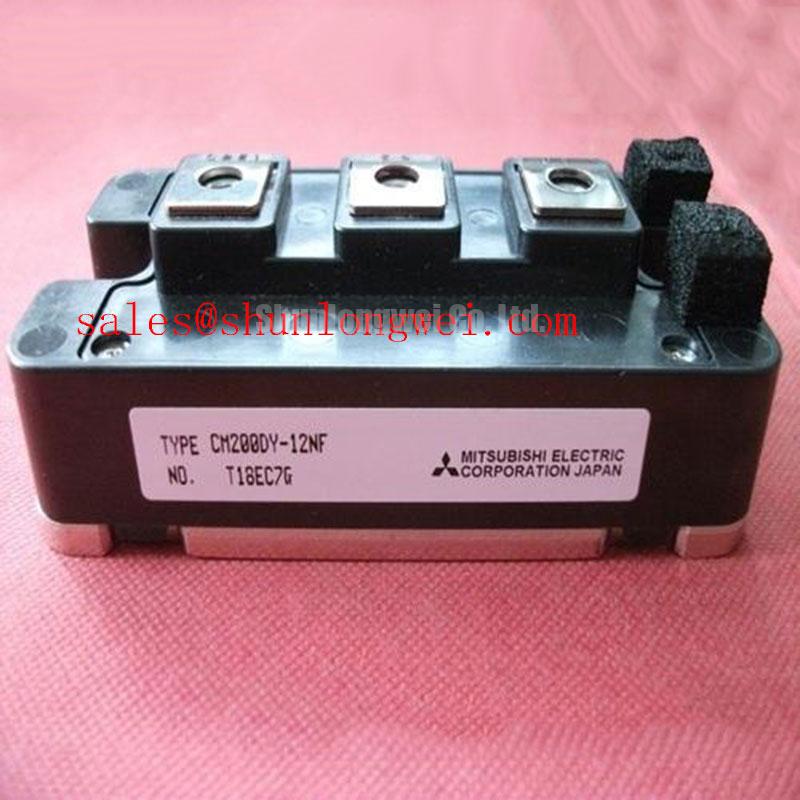
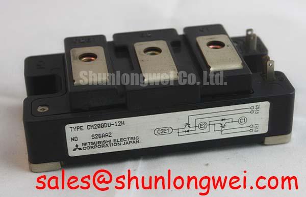
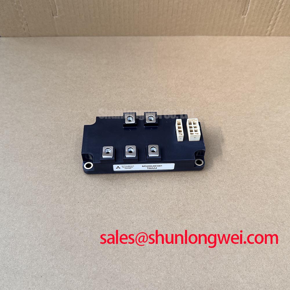
When evaluating a different part number, compare its topology, terminal drawing, voltage and current ratings, gate requirements and thermal interface with the original equipment documentation. The CM15MD-12H has a separate product page for that comparison, but its presence in the same manufacturer’s range does not establish direct interchangeability with CM200TU-12H.