

Content last revised on October 4, 2026
CM200TU-12F Thermal and Electrical Checks: Isolation Boundaries and Practical Tuning
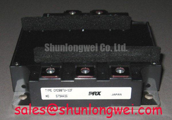
With the DC link discharged, compare cold resistance between the identified power terminals of the CM200TU-12F against the equipment schematic before connecting a gate driver. Confirm the terminal layout from the original module documentation rather than inferring polarity from the case outline. Mitsubishi Electric identifies this part as a 600 V, 200 A IGBT module (Official Specification). Those ratings establish the first screening boundary; they do not establish the permissible bus voltage, pulse duration, heatsink requirement, or suitability for a particular machine.
Start the incoming inspection at the enclosure and terminals. Record visible case damage, terminal condition, and any marking needed to match the machine’s service documentation. With the module isolated from the equipment, a multimeter diode-mode comparison between documented terminals can help reveal a gross short or an unexpected open path. Record probe polarity and meter model with each reading: diode-mode values depend on the meter’s test current and on the path being measured. A plausible cold reading is not proof that the module will switch correctly under load.
For a repair decision, keep the module’s stated 600 V rating separate from isolation requirements elsewhere in the assembly. The rating is an Official Specification for the device; it is not evidence of a reinforced isolation barrier or a specified withstand voltage. Likewise, common-mode transient immunity is normally evaluated for the installed gate-drive isolation path, not assumed from the power module’s voltage rating. As a Design Consideration, an engineer assessing that path should inspect the driver documentation, board clearances, contamination, and routing, then test for unintended gate pulses during controlled switching. Neither a particular isolation test voltage nor a CMTI threshold should be assigned to this installation without the relevant documentation and test plan.
If an insulation test is required, identify exactly which terminals, case surfaces, and external components the proposed test will stress. Disconnect or protect circuitry that the approved service procedure excludes. A low-voltage continuity check cannot establish dielectric integrity, while an improvised high-voltage test can damage connected electronics. The Mitsubishi Electric power semiconductor documentation portal is the appropriate starting point for locating manufacturer documentation before setting device-specific test limits.
💡 Bench Tip: Keep the gate terminals protected from static discharge and compare cold measurements with a documented known-good unit using the same meter and probe polarity.
Benchtop Waveform Tuning and Pulsed Thermal Stress on CM200TU-12F
The 200 A current rating (Official Specification) is a useful identity check, not a stand-alone pulse-overload allowance. Before applying power after a module change, compare the repair assembly with its schematic: gate-driver connections, DC-link polarity, current sensing, heatsink contact, and protection feedback all affect what a switching test can demonstrate. An initial powered test should follow the equipment’s approved procedure, with measurement points chosen before the enclosure is energized.
Capture collector-emitter voltage, current, and gate-emitter voltage during the same switching event where practical. Turn-off overshoot must be assessed against the actual DC-link voltage and the device’s 600 V limit. As a Design Consideration, reducing stray loop inductance and reviewing gate resistance may help control ringing, but a resistor value chosen without the driver’s source and sink capability, switching frequency, and measured waveforms is not a module specification. If a waveform changes after an adjustment, repeat the measurement under comparable load and temperature conditions rather than attributing the change to one component by inspection alone.
Heavy pulses also require a thermal check. Transient thermal impedance describes how junction temperature responds to power applied for a limited time; it cannot be inferred reliably from the continuous current rating. A multi-RC model can be used for an Engineering Calculation when the required manufacturer curves or validated model, pulse profile, and initial case temperature are available. Without those inputs, quoting a peak junction temperature or an allowable overload duration would create false precision. Check the case-temperature measurement method and heatsink interface first, then use the applicable thermal data to evaluate the measured duty cycle.
An industrial inverter welder or medium-frequency induction-heating supply may be a candidate for evaluation, subject to its actual bridge topology, switching conditions, cooling arrangement, and terminal layout. For wider context on how IGBTs are assessed across equipment types, the industrial applications reference is useful; the machine’s own electrical and thermal measurements remain decisive.
Assembly Integrity and Gate-Return Layout for CM200TU-12F
Photograph the original wiring and trace each gate-drive return to its documented terminal before removing the installed module. Do not assume that CM200TU-12F provides a separate Kelvin emitter connection: that feature must be confirmed in the part’s terminal drawing. If the documented configuration does provide an auxiliary emitter return, keeping the driver’s sensing path separate from the main current path is a Design Consideration that can reduce the influence of shared-path voltage transients. If it does not, the board and driver must be evaluated around the connection actually available.
During assembly, inspect the mating surfaces for debris and uneven contact, and check that terminals align without forcing the package into position. Use the mounting sequence, interface material, and tightening requirements specified for the installed hardware. Uneven mechanical contact can complicate a thermal comparison even when cold electrical checks appear unchanged. After mounting, verify that gate wiring has not been routed alongside a high-current conductor simply to accommodate a different terminal position.
For troubleshooting, a gate-voltage trace should be referenced to the driver return point identified on the schematic. A trace taken from a different emitter location may include voltage developed in the power path and can misrepresent the voltage applied at the gate-drive connection. Compare the suspect assembly with a known-good signal path using the same probe arrangement. Ringing may involve layout, driver behavior, measurement technique, or the connected load; the trace alone does not identify a single cause.
The linked CM300DXDX1-24A can be included in a replacement assessment, but it should not be treated as a direct substitute on the basis of its model name or current rating. Verify circuit configuration, pinout, package mounting, voltage and current limits, gate-drive requirements, and thermal fit against both sets of manufacturer documentation. The same discipline applies to every proposed replacement for the CM200TU-12F.
Output-Path Layout, Common-Mode Current, and Equipment Compatibility
At the equipment level, a switching module interacts with bus wiring, load cables, filters, chassis connections, and the gate-drive supply. In an inverter welder, inspect the power path from the DC link through the switching stage to the output network before assigning an observed terminal spike to the module. A CM100DY-12E is another module an engineer might encounter while reviewing related power-stage hardware; its electrical role and compatibility must be established from the actual circuit, not assumed from its proximity in a parts list.
Long output leads can introduce reflected-wave and common-mode behavior that is not visible in a cold module test. If an application uses long motor leads, measure voltage at the relevant equipment and load terminals with suitable instruments, then compare the result with the system’s component limits. Reflections can raise terminal stress, but no fixed spike multiplier should be assigned to a specific installation without its cable, termination, and waveform data. Any output filter or choke should be evaluated for the measured switching waveform, load current, and thermal conditions rather than sized from the module rating alone.
Control behavior belongs in that system-level assessment too. The droop speed control reference describes a control concept, not a characteristic of this IGBT module or a substitute for waveform measurement. Keep control-loop observations separate from power-stage tests: an unstable output may warrant checking both, while a cold resistance reading cannot resolve either question.
Before returning the equipment to service, repeat terminal and insulation checks only as authorized by the machine procedure, confirm protection feedback, and retain comparable switching captures from the final assembly. That record lets the next technician distinguish a measured change in the power path from a difference in probe placement or operating conditions.