
Content last revised on September 10, 2026
Field Diagnostics & Commissioning: Kelvin Emitter Connection in 1MBI300U2H-060L-50 Topologies
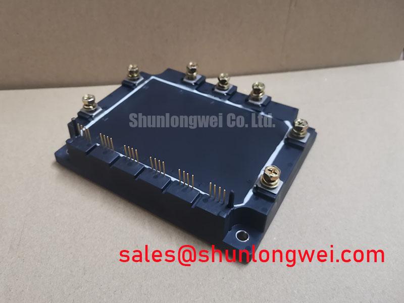
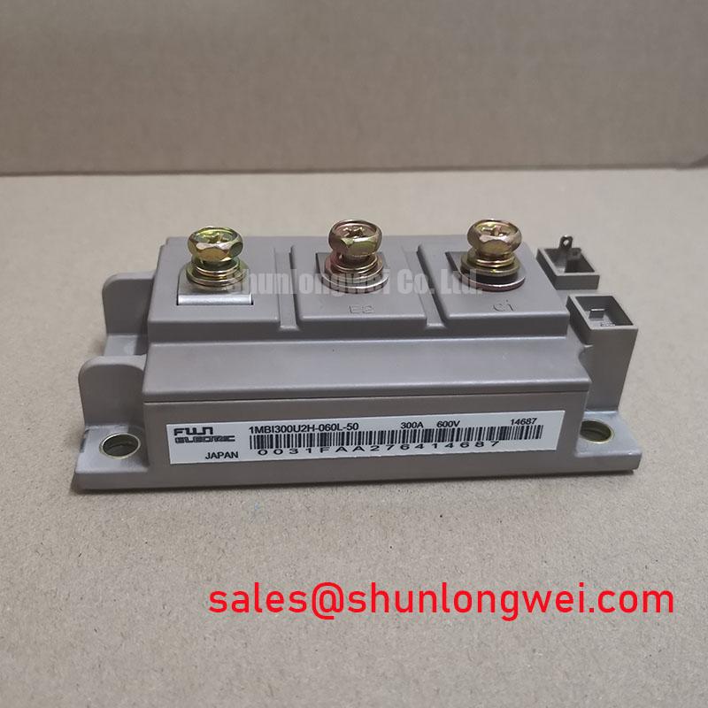
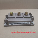
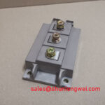
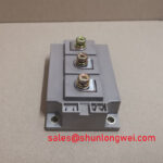
With the drive isolated and the DC link discharged, begin by checking the nameplate against 1MBI300U2H-060L-50, then inspect the module body, terminals, mounting surface, and surrounding busbar for heat damage or mechanical movement. Fuji Electric lists this device as an IGBT module with a specified voltage rating of 600.0 V and a specified current rating of 300.0 A. These ratings identify the replacement class, but the complete drive circuit, switching conditions, cooling arrangement, and protection settings still require verification before energizing a repaired heavy-duty variable frequency AC motor drive.
| Parameter | Official Specification |
|---|---|
| Manufacturer | Fuji Electric |
| Part number | 1MBI300U2H-060L-50 |
| Product category | IGBT Module |
| Rated voltage | 600.0 V |
| Rated current | 300.0 A |
| Package | Module |
During a field replacement, do not assume that a control return conductor and a high-current emitter path can share any convenient copper route. The gate driver reference should follow the terminal arrangement documented for the original assembly, while the power emitter path should remain physically separate from sensitive gate-return wiring wherever the topology permits. This is a Design Consideration intended to reduce emitter mutual coupling, common-mode ground bounce, and unwanted gate oscillation.
Before connecting the driver, use the unpowered assembly for a comparative cold-state inspection. Check for unintended continuity between gate, emitter, and collector terminals, compare the readings with a known-good phase, and look for contamination or a damaged insulating interface. A resistance reading alone does not prove semiconductor health, so suspicious results should be followed by controlled diode and insulation checks using procedures appropriate to the complete drive.
At commissioning, monitor the gate-to-emitter waveform at the module terminals rather than relying only on a driver-board test point. A mismatch between the command waveform and the terminal waveform may indicate excessive loop inductance, a poor reference connection, probe-ground interference, or a damaged gate circuit. Keep the gate loop compact, route outgoing and return conductors together, and have the system engineer verify switching overshoot and false turn-on under the actual DC-link and motor-load conditions.
For a regenerative braking branch, the module may be evaluated as part of a chopper and braking-resistor energy path, subject to the converter topology and the complete semiconductor ratings. Fuji Electric’s Brake Chopper IGBT Modules reference provides useful manufacturer-level context for this circuit function. It should not be treated as confirmation of every electrical or thermal characteristic of this specific part number.
Benchtop Waveform Tuning: Mitigating Stress via Transient Thermal Impedance on 1MBI300U2H-060L-50
Heavy pulsed operation requires the repair engineer to separate electrical stress from thermal stress. An oscilloscope should capture collector-emitter voltage, gate-to-emitter voltage, current, and the timing relationship between the switching command and the load current. When a brake chopper operates with a large resistor bank, the measured pulse width, repetition pattern, and cooling conditions determine the thermal response. The official 600.0 V voltage and 300.0 A current ratings are essential boundaries, but they do not by themselves define a permissible overload pulse.
A transient thermal impedance model can be used as an Engineering Calculation when the applicable junction-to-case data and case-temperature measurement are available from the relevant Fuji Electric documentation. The engineer can represent the thermal path with several RC sections, apply the actual pulsed power history, and compare the calculated junction-temperature rise with the documented operating limits. If those thermal-network parameters are unavailable, use conservative bench testing and direct temperature observation rather than inventing a device-specific transient curve.
Phase-angle conduction, low-frequency load variation, and DC-link ripple can produce very different heating patterns even when the average output power appears similar. Check the brake command, resistor current, DC-link voltage, and heat-sink temperature over the complete operating cycle. Line-frequency ripple smoothing and control-loop changes should be assessed as system-level measures, with the resulting semiconductor loss verified by waveform capture and thermal testing.
An RC snubber can reduce ringing when the measured oscillation is associated with a defined commutation loop. Its values should be selected from the observed waveform, parasitic network, pulse energy, and component voltage stress. Do not transfer snubber values from another Fuji module without checking the physical layout and switching behavior of the repaired drive. Engineers evaluating a related system topology may also review the 2MBI150UC-120 as a neutral reference for a related power-conversion stage, not as an automatic substitute.
1MBI300U2H-060L-50 Circuit Protection & Reliability: Calibrating Derating Guidelines and Mismatched Parameters
Protection coordination should begin with the actual fault paths: short-circuit detection, gate-drive shutdown, DC-link isolation, braking control, and thermal feedback. The module’s official voltage and current ratings must be compared with the measured operating envelope, switching transients, fault duration, and cooling conditions. A protection threshold that appears acceptable on a schematic may respond too slowly after wiring inductance, sensor delay, and driver propagation time are included.
Parallel-current behavior also deserves bench verification. The positive temperature coefficient commonly associated with conduction voltage can support static current sharing in suitable parallel arrangements, but dynamic sharing remains strongly affected by gate-loop symmetry, emitter coupling, stray inductance, driver impedance, and timing mismatch. This is a Design Consideration, not a guarantee that parallel operation is suitable for this specific module. Match the physical gate wiring and power paths as closely as practical, then confirm current balance with current probes during controlled switching tests.
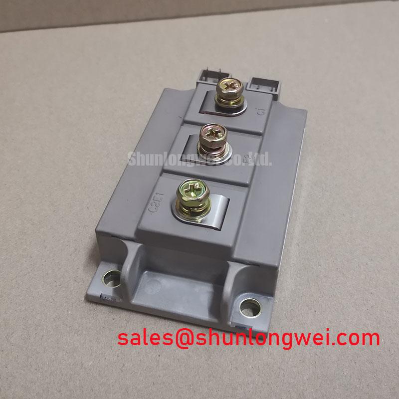
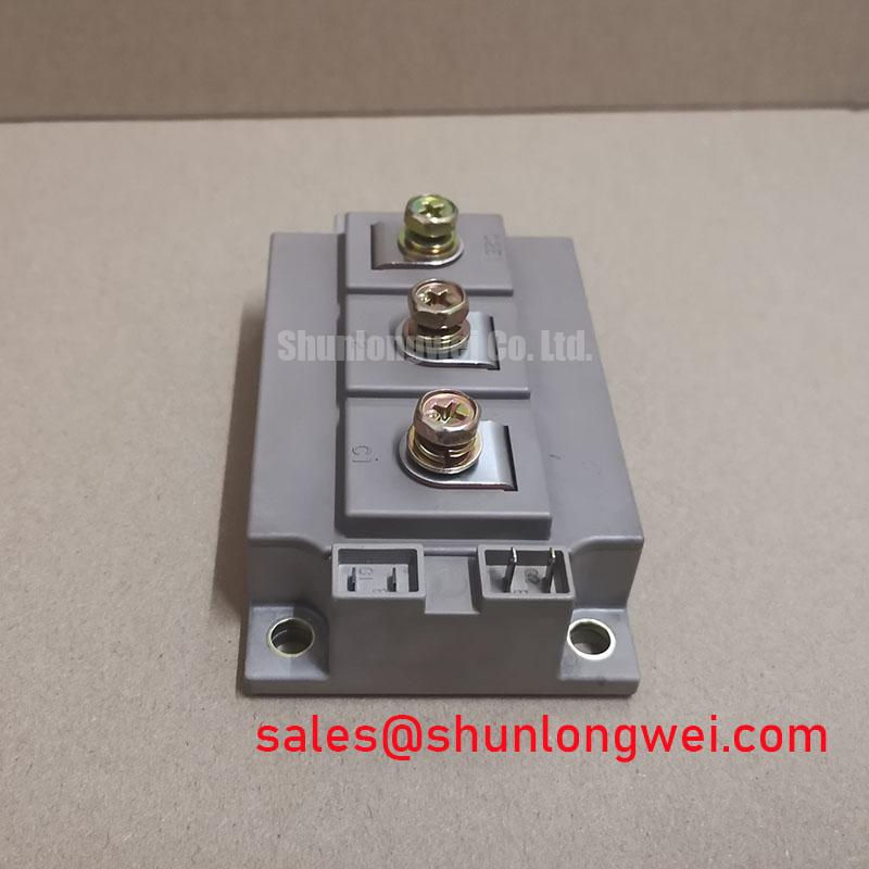
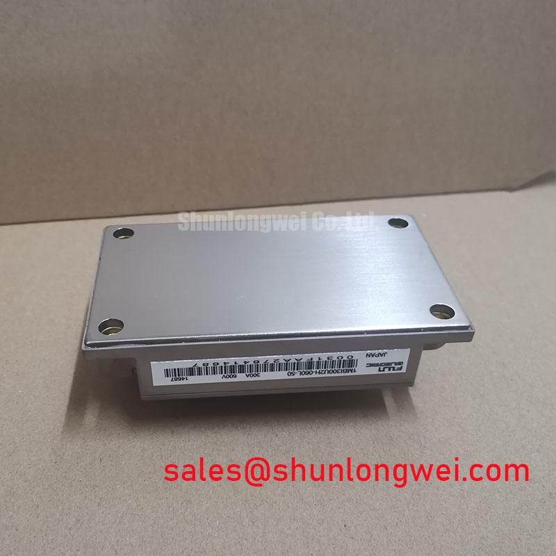
Terminal spacing, creepage, clearance, busbar insulation, and contamination control must be assessed against the DC-link environment and the applicable equipment standard. The module package designation is officially listed as Module; no package dimensions or terminal spacing should be assumed without the relevant mechanical drawing. When installing the replacement, confirm the original busbar orientation, connector keying, clamping method, and heat-transfer interface before applying power.
⚠️ Field Alert: Disconnect power and verify the discharged DC link before touching the module, gate cable, braking resistor wiring, or control reference connections.
For broader system-level context on IGBT use in demanding power-conversion equipment, engineers can consult the Industrial Applications guide. It should support design review, while the final protection and reliability decisions remain dependent on measured system conditions and applicable standards.
Benchtop Waveform Tuning: Mitigating Stress via Suppression of 2x VDC Voltage Doubling at 1MBI300U2H-060L-50
Long motor leads can create a reflected-wave condition in which the terminal voltage rises substantially above the local inverter waveform. A severe measurement can approach twice the applied step under particular cable, termination, and load conditions, but the exact peak is installation-dependent. Capture the waveform at the module output terminals and at the motor end with properly rated differential probes. Probe placement, bandwidth, grounding, and cable routing must be checked before assigning the spike to the IGBT itself.
The first corrective principle is to minimize the commutation loop and busbar parasitic inductance so that turn-off current change does not create unnecessary voltage overshoot. The system designer should verify peak collector-emitter voltage against the 600.0 V official rating during switching tests, including regenerative operation and abnormal load transitions. A laminated busbar, short power return, close DC-link decoupling, and symmetrical phase construction may help, but the final geometry must be validated on the actual drive.
When the motor cable is the dominant source of ringing, an output choke, dv/dt filter, or sinusoidal filter may be considered according to motor insulation limits, cable length, switching frequency, leakage current, and drive-control requirements. Filter selection is a system calculation rather than a fixed prescription for this module. Recheck the gate waveform after fitting the filter because altered commutation behavior can change turn-off overshoot and conducted noise.
During the final test, increase operating conditions in controlled stages while recording DC-link voltage, phase current, collector-emitter voltage, gate-to-emitter voltage, and heat-sink temperature. If one phase behaves differently, compare its terminal impedance, gate-return routing, busbar torque, sensor position, and driver timing with the other phases before replacing additional power devices. The 2MBI300U4H-120-50 may be reviewed as a separate Fuji Electric module for cross-reference analysis, but voltage class, current capability, package mechanics, and gate-drive requirements must be confirmed independently.