

Content last revised on September 25, 2026
NEC NL3224BC35-22 Inspection and Integration
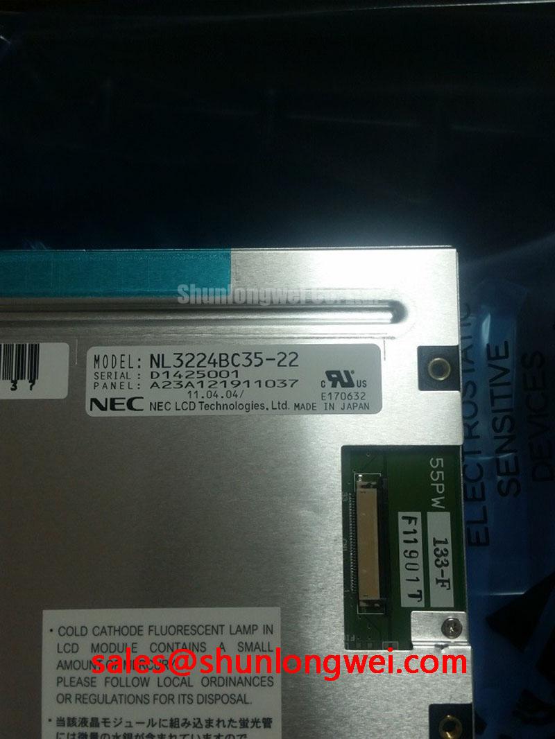
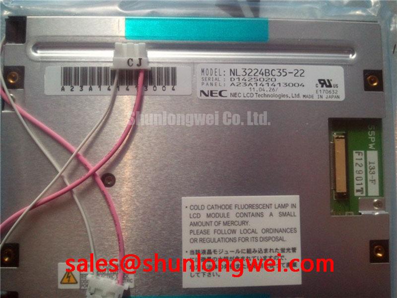
Inspect the NEC NL3224BC35-22 before installation by checking the module label, connector condition, visible glass damage, frame deformation, and the original equipment documentation. The available factory context identifies this unit as an industrial grade LCD/HMI panel in a TFT-LCD display module format. The original panel documentation remains the controlling source for electrical timing, supply requirements, connector pin assignment, backlight architecture, optical data, and mechanical dimensions.
| Item | Reference information |
|---|---|
| Model | NL3224BC35-22 |
| Manufacturer | NEC |
| Product category | Industrial Grade LCD/HMI Panel |
| Construction category | TFT-LCD Display Module |
| Specification status | Verify against the original factory documentation |
| Primary evaluation scope | Physical interface, display timing, backlight compatibility, touch integration, enclosure fit, and system-level EMC verification |
The NEC NL3224BC35-22 product reference should be checked against the display removed from the equipment. This is especially important when the replacement is being evaluated for a railway passenger information system, cab signalling display, industrial HMI, or another embedded operator interface. A similar-looking panel can still differ in connector orientation, active-area position, backlight drive method, image format, or mounting-hole placement. The system integrator should verify the required supply voltage from the original panel documentation rather than infer it from the model appearance.
Industrial EMI Noise Immunity, Chassis Shielding Continuity and Common-Mode Ferrite Chokes
Begin the electromagnetic compatibility review at the cable entry point. A display installed near a variable-frequency motor drive, inverter cabinet, traction auxiliary converter, or switching power supply can experience conducted and radiated interference through the video cable, backlight wiring, touch interface, and chassis. Pixel jitter, unstable image content, horizontal noise bands, or intermittent loss of synchronization should be investigated across the complete signal path instead of being assigned to the display module without measurement.
For an LVDS implementation, designers should preserve the intended differential routing geometry from the host board to the panel connector. The cable shield should have a low-impedance connection to the equipment chassis where the enclosure and grounding architecture require it. A long drain wire or a narrow pigtail connection can change the high-frequency return path and may reduce shielding effectiveness. The correct bonding arrangement remains system-dependent because protective earth, signal reference, chassis structure, and isolation requirements vary between equipment platforms.
Common-mode ferrite components can be evaluated when interference is coupled onto the cable as a common-mode current. Their impedance profile should be reviewed against the disturbance spectrum, signal data rate, startup behavior, and allowable waveform distortion. A component selected only by its nominal impedance may introduce unwanted loss or edge deformation. Designers should verify the result with a known-good display signal path and an oscilloscope while the nearby switching equipment operates through its relevant load range.
PWM backlight control also requires system-level checking. A proposed control range such as 200 Hz to 1 kHz may be used as a bench evaluation range for visual flicker and audible interaction, but it is not an official specification of the NEC NL3224BC35-22 unless confirmed by the original technical documentation. Observe luminance response, camera-band interaction, acoustic behavior from the driver assembly, and duty-cycle linearity. If the panel includes a separate backlight driver, the host system should verify whether the module expects enable control, analog dimming, PWM input, or a dedicated constant-current interface.
Touch functionality must not be assumed from the LCD/HMI category alone. If the host equipment uses a resistive or capacitive touch layer, confirm that the touch sensor, controller, flex cable, and mechanical overlay belong to the replacement assembly or are transferred according to the original service design. Gloved operation and operation with moisture on the surface should be validated using the actual cover material, controller firmware, grounding scheme, and enclosure. These behaviors are not established by the available factory identification alone.
💡 Pro Tip: Keep the high-speed differential pairs routed as a controlled, symmetrical path and verify their signal quality at the panel connector rather than relying only on continuity testing.
Incoming Benchtop Inspection: COG and TAB ACF Integrity
Incoming inspection should separate visible optical faults from electrical interface faults before the panel is fitted into the machine. Under controlled lighting, examine the glass perimeter, frame, connector tail, flexible cables, bezel, and any exposed bonding region for impact marks, lifted edges, contamination, or mechanical stress. Do not press directly on the active display area during this check. A panel that passes a static visual inspection can still show intermittent line behavior after the frame is tightened, so the test fixture should reproduce the intended support points without adding pressure to the glass.
A practical three-stage color test can be performed with full-screen red, green, and blue images. Use each primary field to expose different classes of visible defects, then repeat the check at low and high brightness. Look for fixed lines, clusters of abnormal pixels, uneven illumination, transient bands, and areas that change when the signal source or backlight setting changes. This procedure identifies observable behavior; it does not establish a supplier-specific defect threshold or a field failure rate.
A 45-degree flashlight inspection can help distinguish surface contamination, cover reflections, diffuser irregularity, and dark regions that are not obvious in a normal viewing position. A dark shadow that remains in the same location while the displayed color changes may require backlight and optical inspection. A line defect that follows image content or remains tied to a particular row or column may require investigation of the display driver path, connector seating, or bonded interconnect. These observations are diagnostic clues rather than single-cause conclusions.
COG and TAB bonding areas should be evaluated without applying localized pressure. An intermittent line that appears after flexing the assembly may indicate a mechanical or interconnect issue, but confirmation requires comparison with the signal source, connector condition, frame stress, and temperature behavior. Use the original service method for any cleaning or reseating procedure. Avoid solvents or tools that can damage exposed flexible circuits or alter the bonding surface.
Temperature testing requires caution because liquid-crystal response can change at low ambient temperature. When the equipment specification calls for operation around −20 °C to −30 °C, the complete display assembly should be evaluated in a controlled chamber with the actual startup sequence, video timing, backlight condition, and enclosure airflow. Slower gray transitions, temporary contrast changes, or delayed image stabilization may involve the panel, the driver electronics, the power supply, or the thermal state of the assembly. A heater strip should be considered only as part of a system thermal design, with its control behavior verified against the panel manufacturer’s documented limits.
When a display fails to start, record the order and timing of host power, logic supply, backlight enable, and video activity. The system integrator should compare these signals with the original panel documentation and a known-good unit. Do not apply an assumed supply or backlight voltage merely because another TFT module uses it.
Normally White TN Grayscale Inversion Mitigation and Viewing Direction Alignment
The viewing direction should be checked during the actual equipment task rather than judged from a front-facing bench position. A driver display, passenger information terminal, and industrial HMI may place the viewer below, above, or to one side of the optical axis. TN panels can show angle-dependent grayscale behavior, so a gray test pattern should be viewed from the intended operator position and from the practical limits created by the enclosure.
Grayscale inversion is best investigated with near-gray patterns, moving graphics, and text transitions. Check whether adjacent gray levels change order or lose separation as the observer moves vertically or horizontally. If the display is installed behind a window, protective cover, or angled bezel, include that optical stack in the evaluation. The final result can be affected by cover reflection, surface treatment, ambient illumination, and the position of the display relative to the operator.
The normally white characteristic should be confirmed from the original technical documentation rather than inferred from a replacement listing. Likewise, a full symmetric viewing cone such as 85 degrees in four directions must not be attributed to this model without a verified factory optical table. IPS, MVA, and TN technologies have different viewing behavior, and a visually similar replacement can produce a different grayscale result even when its outline appears compatible.
Surface treatment is equally important in bright control rooms and outdoor-facing passenger information equipment. Anti-glare and anti-reflective behavior should be evaluated with the production cover, ambient light, and cleaning method. A matte surface can reduce mirror-like reflections while also affecting perceived sharpness and contrast. A glossy surface can preserve apparent clarity but create strong reflections from lamps, windows, or sunlight. The correct choice depends on the enclosure and task lighting, not on the LCD model number alone.
Claims such as contrast above 500:1 at 50,000 lux require a documented measurement method, viewing angle, luminance condition, and panel configuration. They should not be presented as an official NL3224BC35-22 specification without a source. For sunlight-facing equipment, evaluate legibility using real interface graphics, warning colors, fine text, and dimmed as well as full-brightness operation. The backlight driver, optical stack, cover glass, and surface treatment all influence the result.
Use the same procedure when comparing a candidate reference such as NL10276BC16-06. A comparison should cover active image area, resolution, connector and timing compatibility, mounting geometry, optical direction, backlight control, and touch arrangement. Similar product families do not establish interchangeability by themselves.
Diffuser Film and Prism Sheet Thermal Buckling Prevention under Continuous Full-Duty Operation
Continuous full-duty operation should be evaluated with the panel mounted in the target enclosure, because the thermal condition at the display edge can differ substantially from an open-bench test. Record the temperature distribution around the bezel, backlight region, driver board, cable entry, and nearby heat sources. A localized hot area may come from the backlight driver, restricted airflow, an adjacent converter, or mechanical contact with the enclosure.
An aluminum heat-spreader rail may be considered where the equipment structure creates an uneven thermal path, but its position must be checked against the active area, frame, cables, insulation, and service clearances. The rail should not press against the glass or optical layers. Any thermal interface material, bracket, or clamp must be selected and validated for the assembly’s mechanical tolerance and temperature range. The panel documentation should control the permitted mounting method.
Optical films can move or develop visible nonuniformity when temperature gradients, enclosure pressure, and mechanical restraint interact. Do not attribute every bright or dark patch to diffuser damage. Compare the symptom at startup, after thermal soak, with different backlight levels, and after the assembly returns to ambient temperature. A fixed mark, a temperature-dependent patch, and a backlight control artifact require different inspection paths.
Backlight longevity claims such as L70 or B50 require a manufacturer test definition, drive condition, ambient temperature, and sampling method. No such lifetime value is established in the available factory information for this product page, so a specific operating-hour promise should not be assigned to the NEC NL3224BC35-22. The system designer should verify the actual backlight architecture and its open-load, short-load, overvoltage, and thermal protection behavior from the original documentation and driver specification.
For backlight fault diagnosis, first isolate the host control signal from the backlight power path. Confirm whether the display image is present while illumination is absent, then inspect the driver input, enable state, current regulation, and protection response using the approved test method. A dark screen can also result from missing logic power, absent video timing, a connector problem, or a host sequencing issue. Avoid applying an external backlight source until the original electrical requirements are confirmed.
When integrating the panel into a railway passenger information system or cab signalling display, designers should verify the enclosure opening, bezel compression, connector bend radius, viewing direction, ambient-light performance, touch behavior, and thermal condition as one mechanical and electrical assembly. The practical installation and test principles described in The Ultimate Guide to Industrial TFT LCD Technology can be used as an additional reference during system evaluation.