Content last revised on October 9, 2026
Preventing Frame Lag & Image Smearing in Cryogenic Storage & Outdoor Industrial Facilities
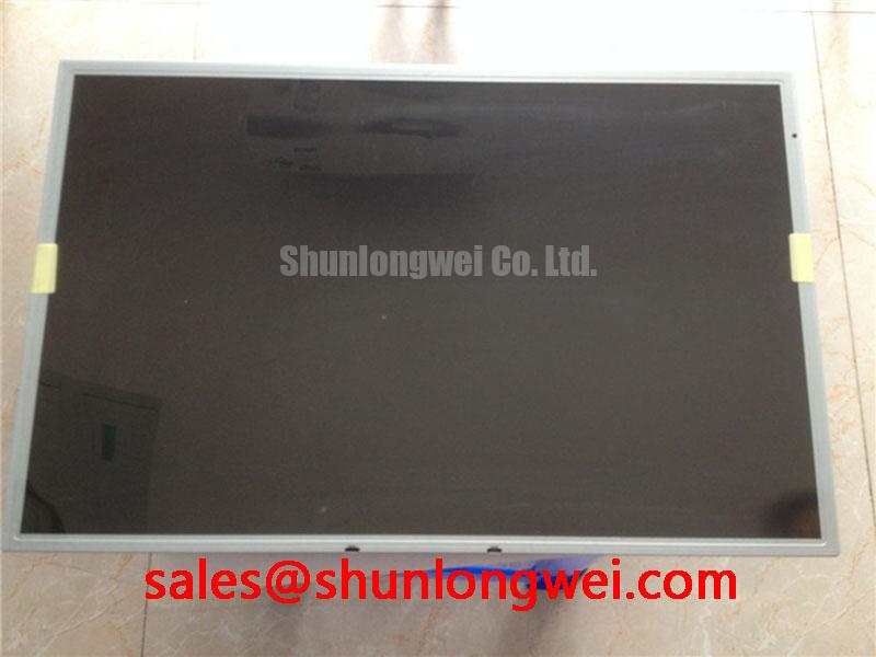
| Model | LM190E08-TLJ8 |
| Manufacturer | LG Display |
| Product category | Industrial Grade LCD/HMI Panel |
| Display technology | TFT LCD Active Matrix Color Display Module |
| Specification status | Decoded Baseline / Standard Form Factor |
| Electrical and optical values | Verify against the panel documentation used in the original equipment |
Check the displayed motion pattern at the actual operating temperature before approving LM190E08-TLJ8 for a replacement build, because liquid crystal viscosity changes with temperature and can alter perceived gray to gray response. A moving grayscale test image, scrolling diagnostic text, and a dark to bright transition provide more useful evidence than a static color screen when investigating image smearing.
The manufacturer identifies this part as an LG Display TFT LCD Active Matrix Color Display Module in an industrial HMI panel format. The model identity alone does not establish a particular response time, refresh setting, backlight lifetime, or operating temperature range. Those values should be matched to the source panel documentation and the equipment service specification before installation in a cryogenic cabinet or outdoor enclosure.
Across repeated sub zero and elevated temperature cycles, inspect the perimeter sealing system for distortion, lifting, or signs of moisture migration. Seal stability is a mechanical integration issue as much as a display issue. A rigid bezel, uneven compression, or enclosure flex can transfer stress into the active area and create visible nonuniformity after thermal cycling. Designers should allow the enclosure and display mounting system to accommodate differential expansion rather than treating the panel as a structural member.
Backlight assessment should be performed with the installed constant current driver, not with an unrelated bench supply. Record luminance at consistent image content and ambient conditions, then compare center and edge uniformity over the planned maintenance interval. A quoted backlight life figure such as 50,000 hours to 50 percent brightness must come from the applicable backlight specification or test report; it should not be assigned to this model without source documentation.
For display technology background, the discussion of industrial TFT operating principles and common selection issues in The Ultimate Guide to Industrial TFT LCD Technology provides useful context for response behavior, optical integration, and service evaluation. When comparing a same size class reference, engineers may also review LQ190E1LW42 as a separate model rather than assuming interchangeability.
Shielded FFC/FPC Flat Flexible Cable Grounding across 360 Degree Connector Shells
Route the display cable away from high current motor conductors first, then evaluate the complete shield termination from the panel connector shell to the equipment chassis. In cabinets containing variable frequency drives, pixel jitter or horizontal noise bands can result from coupling through cable geometry, return current paths, connector reference points, or common mode noise. The observed symptom should be compared with the signal at the transmitter and receiver so that a display fault is not confused with a source timing problem.
The interface type, pin assignment, supply requirements, clock relationship, and data timing for LM190E08-TLJ8 must follow the original panel documentation and the host controller design. Do not infer TTL or LVDS compatibility from the product category alone. When the original system uses a shielded FFC or FPC, preserve the intended contact orientation, ground reference, bend clearance, and retention force. A cable that fits mechanically may still create an incorrect electrical return path.
A 360 degree connector shell termination can reduce exposed shield length when it is implemented correctly, but the enclosure bonding method remains system dependent. Engineers should check continuity and bonding with power removed, then observe common mode behavior while the motor drive changes operating state. Ferrite components can be evaluated as a design option when conducted or radiated noise remains after cable routing and grounding have been corrected; their impedance characteristics must match the disturbance frequency rather than being selected by appearance alone.
Clock jitter and data hold margin should be checked at the receiving interface over the intended temperature window. Use the known good signal path as the comparison reference and inspect edge quality, ringing, overshoot, and timing displacement with suitable probing. The panel listing does not establish a universal clock rate or skew limit for every host implementation, so the controller, cable, and panel documentation must be treated as one interface set.
Maintenance Note: Disconnect cabinet power before removing or inserting the FFC or FPC, and inspect the connector latch and shield contact during every service intervention.
Super IPS / MVA Wide Symmetric Viewing Cone for Multi Angle Consoles
Evaluate the display from the actual operator positions before approving a multi angle console installation, using grayscale ramps and skin tone images rather than relying only on a front view. TN panels can show grayscale inversion and color changes as the viewing angle shifts, while IPS and MVA technologies may offer broader visual consistency depending on the specific panel construction and optical stack.
LM190E08-TLJ8 is identified by the supplied product data as a TFT LCD active matrix color display module, but the available baseline information does not establish a Super IPS or MVA classification, a symmetric 85 degree viewing specification, an anti glare surface grade, or a contrast ratio under direct sunlight. These features must be confirmed from the original technical documentation before being used as replacement acceptance criteria.
Ambient light testing should reproduce the intended console position, viewing direction, enclosure window, and task lighting. Reflections from surgical navigation equipment or ultrasound operator consoles can reduce perceived contrast even when the panel produces a satisfactory image in a dark workshop. Surface treatments, cover glass, optical bonding, and bezel geometry all influence the result. The reference material on optical diffusers and brightness enhancement films explains how backlight optical elements affect brightness distribution and viewing performance.
For industrial display technology comparisons, the Kyocera Industrial TFT LCD Display Technologies resource offers useful industry context. It should be used for general technology understanding, not as evidence that a particular optical construction belongs to LM190E08-TLJ8.
In high precision surgical navigation and ultrasound diagnostic display terminals, engineers should assess grayscale visibility, reflected glare, image uniformity, and operator viewing position as a combined human factors requirement. The panel can be considered for such equipment only after the host electronics, optical cover, enclosure, and applicable medical equipment requirements have been evaluated together.
Thermal Expansion Clearance Sizing across Heavy Industrial Metal Enclosure Cutouts
Measure the enclosure cutout, bezel contact surfaces, and mounting hole pattern before tightening any fastener around LM190E08-TLJ8. The display should be supported evenly without forcing the active area, bezel, or optical stack to compensate for a distorted metal panel. Localized pressure can appear as bright or dark regions, edge nonuniformity, or changing mura after the enclosure heats and cools.
The supplied product information confirms a standard form factor but does not provide a verified outer bezel drawing, mounting hole tolerance, or manufacturer specified M3 torque limit for this model. Those dimensions must come from the mechanical drawing used for the original assembly. A cross pattern is a reasonable installation method when the frame design requires progressive load distribution, but the final torque remains determined by the fastener, bracket, thread material, gasket compression, and panel drawing.
Thermal expansion clearance should be considered between the metal enclosure, mounting bracket, front bezel, and display module. Designers should prevent hard contact at unsupported corners while maintaining the sealing function required by the equipment. If a gasket is used, inspect its seating path for folds, compression gaps, and contamination. An enclosure that is dust resistant in the static workshop may lose that performance after repeated thermal movement or service access.
Signal integrity belongs in the same mechanical review when the display cable passes near servo or inverter wiring. For a differential interface, preserve pair symmetry, limit unnecessary stubs, and maintain the intended reference path through bends and connector transitions. A nominal 100 ohm differential target may be used only when it is specified by the actual interface design; the panel model data supplied here does not independently establish a universal impedance or skew requirement. Validate eye opening and timing at the receiver after the cable is installed in the final metal enclosure.
After assembly, run a dark field, full white field, grayscale ramp, and moving image while the enclosure reaches its normal thermal condition. Check for changes near fasteners, corners, cable exits, and gasket contact regions. This procedure helps separate mechanical stress effects from backlight uniformity, source timing, and optical reflection issues without assigning a single cause to every visible defect.