

Content last revised on September 21, 2026
Assembly Integrity & Layout Architecture: Optimizing Heatsink Contact Pressure for QM75DY-H
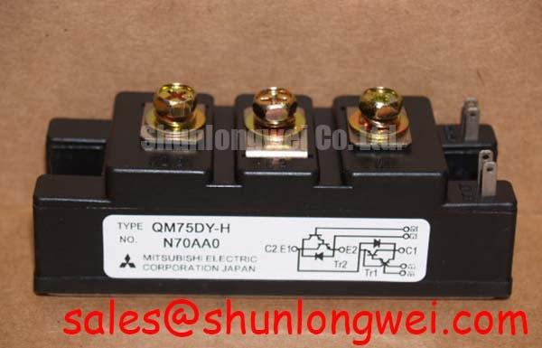
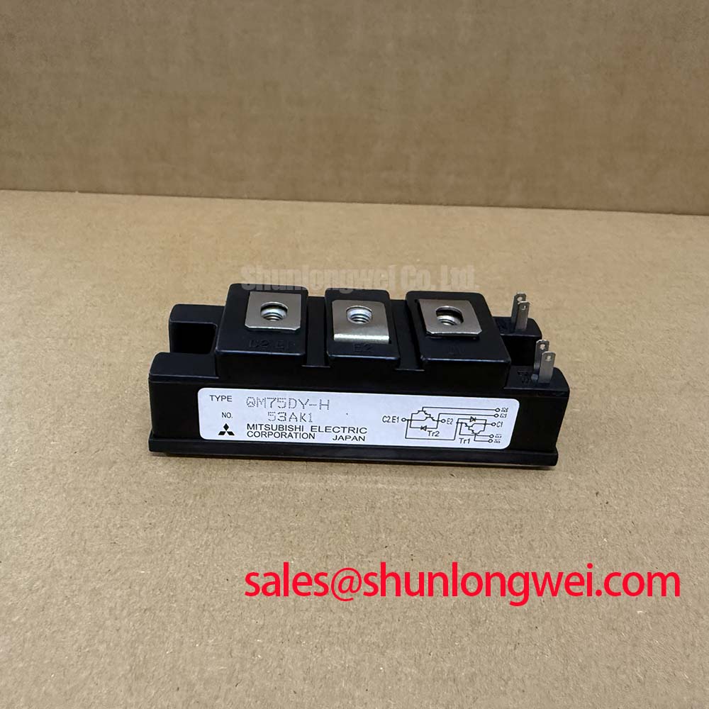
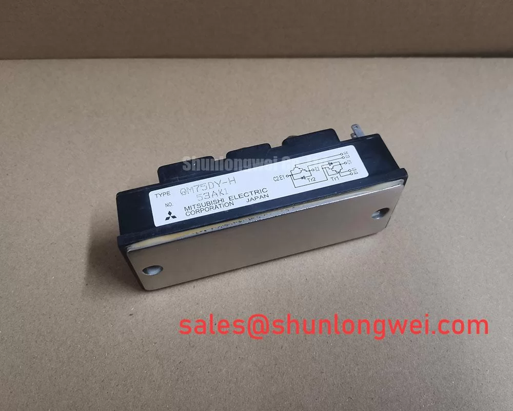
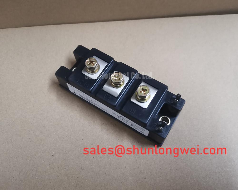
The Mitsubishi Electric QM75DY-H is an Isolated Darlington Module rated at 600.0 V and 75.0 A as an Official Specification. Its isolation arrangement can simplify mechanical integration, but it does not remove the need to verify the system’s required creepage distance, clearance, protective earthing arrangement, and enclosure insulation coordination.
For heatsink assembly, Design Consideration calls for a clean, flat contact area and an even thermal interface material layer. A controlled thermal interface material thickness in the general range of 50 to 100 um can help compensate for minor surface variation while avoiding excessive material that raises thermal resistance. The actual material, thickness, and mounting process must be validated against the heatsink flatness and the original equipment service requirements.
Apply mounting screw preload in a progressive cross-pattern sequence so the baseplate seats uniformly. If the removed module shows an uneven thermal compound imprint, localized discoloration, or evidence of poor contact, inspect the heatsink surface and mounting hardware before fitting the replacement. Field Alert: Disconnect and verify the DC link is discharged before removing or reconnecting any power terminal cables.
Keep the DC bus path and gate-drive return path physically organized around the original topology. Design Consideration favors low-inductance, symmetrical conductor routing to limit turn-off overshoot, with peak voltage margin verified by switching measurement in the completed system.
| Parameter | Value | Classification |
|---|---|---|
| Manufacturer | Mitsubishi Electric | Official identification |
| Module model | QM75DY-H | Official identification |
| Rated voltage | 600.0 V | Official Specification |
| Rated current | 75.0 A | Official Specification |
| Package | Isolated Darlington Module | Official Specification |
Field Diagnostics & Commissioning: Derating Guidelines and Mismatched Parameters in QM75DY-H Topologies
During commissioning, compare the module position, busbar arrangement, drive-board connections, cooling path, and protection wiring with the known operating channel before applying full power. A Darlington module’s on-state behavior changes with junction temperature, so parallel operation should be assessed as a system rather than assumed from the current marking alone.
Design Consideration recognizes that a positive temperature coefficient of VCE(sat) can support steady-state current-sharing behavior under suitable conditions. Dynamic sharing remains dependent on matched gate-loop wiring, common busbar geometry, driver timing, and measured switching waveforms. Designers should verify current distribution and collector-emitter voltage behavior under the intended operating load rather than infer balance from static measurements alone.
Derating is system-determined by DC-link voltage, switching conditions, thermal path, ambient environment, and the original converter control strategy. In commercial string inverter and micro-grid energy-storage service, technicians should distinguish a module-related condition from an upstream sensing, control, or interlock issue. Signal paths associated with industrial sensors may use networked architectures such as IO-Link Open Communications Protocol for Industrial Sensors and Actuators; their interface status should be checked against the equipment documentation.
When reviewing an alternative position or parts record, QM200HA-HK can be considered as a separate module reference for engineering comparison. Its suitability is not established by package family or current marking alone; the system integrator must verify all electrical, mechanical, driver, protection, and thermal requirements.
Preventing Spurious Faults: Desaturation Detection Guidelines for QM75DY-H
Desaturation protection should be reviewed against the original gate-driver architecture before a QM75DY-H is returned to service. A rising collector-emitter voltage during commanded conduction can be associated with overload, a shorted load path, inadequate gate drive, an interrupted gate connection, or a measurement-path problem. Oscilloscope measurements referenced to the approved test method can separate these possibilities without assigning a single cause from one symptom.
For short-circuit response, Engineering Recommendation is to validate detection delay, blanking behavior, and the controller’s shutdown sequence against the module’s applicable safe-operating boundaries and the converter’s measured stray inductance. A controlled soft turn-off approach is often evaluated to reduce inductive overvoltage during fault interruption, but its implementation must remain consistent with the original driver and protection design.
Check the semiconductor fuse coordination from the actual converter documentation. Fuse I2t capability, available fault energy, conductor geometry, and protection response form one coordinated system; the module rating alone cannot establish a safe fuse selection. Gate-driver isolation also requires attention to common-mode transient behavior, grounding, and probe placement during testing.
For current measurement troubleshooting, verify the installed sensor’s offset, bandwidth, mounting condition, and signal reference. The operating principles behind Giant Magnetoresistance (GMR) and TMR Sensors for Industrial Current Measurement provide useful context, while the equipment manufacturer’s calibration procedure remains controlling.
Preventing Spurious Faults: Four-Quadrant Power Flow Topologies for Grid-Connected Storage
In a four-quadrant power stage, energy may transfer between DC battery racks and an inverter DC link in either direction. The QM75DY-H must therefore be evaluated in the installed switching position, including its commanded state, freewheel path, busbar polarity, protection logic, and cooling condition. A replacement module can be electrically correct yet still experience abnormal stress if a companion device, driver channel, snubber network, or DC-link connection has not been checked.
Heavy charge and discharge transitions can create repeated thermal movement across the power assembly. Design Consideration is to inspect heatsink contact consistency, power-terminal tightness, gate-loop symmetry, and cooling performance after controlled commissioning. Monitor the actual converter waveforms and temperatures under permitted test conditions, then compare them with the equipment’s approved acceptance limits.
To investigate switching-related ringing or unexplained protection trips, inspect the DC-link capacitor connection, busbar overlap, driver return routing, and measurement reference before changing component values. The discussion in The 1200 V CoolSiC™ MOSFET Advantage in Three can provide broader context on three-phase power-conversion switching considerations, while the QM75DY-H installation must remain governed by its documented 600.0 V, 75.0 A, and isolated Darlington module requirements.