

Content last revised on September 25, 2026
20-Pin/30-Pin Differential LVDS Timing, Pixel Clock and Skew Compensation
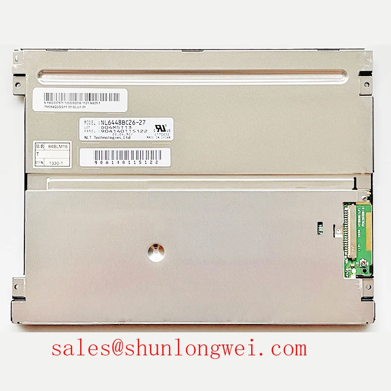
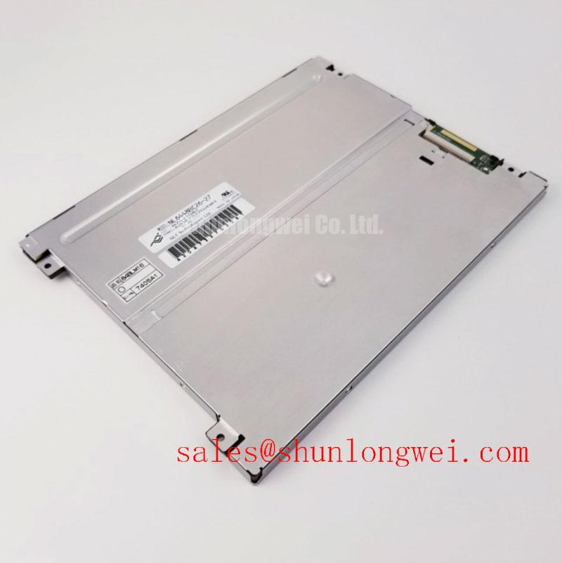
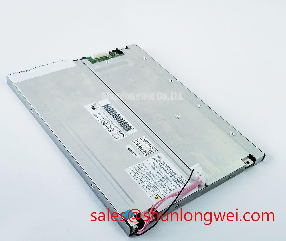
Begin the service inspection by isolating the CNC operator panel or robot teach pendant, recording the panel label, and comparing the installed connector, mounting geometry, and display behavior with the original documentation for NL6448BC26-09. This product is identified as an NEC industrial grade LCD/HMI panel using a TFT LCD display module construction. The verified product information does not establish a universal replacement pinout, supply voltage, backlight specification, viewing angle, or lifetime rating, so those values must be confirmed against the panel documentation and the host equipment before installation.
| Model | NL6448BC26-09 |
| Manufacturer | NEC |
| Product category | Industrial Grade LCD/HMI Panel |
| Module type | TFT-LCD Display Module |
| Specification status | Official Factory Spec Verified |
| Typical evaluation context | Industrial automation CNC operator panels and robot teach pendants |
For repair purchasing, the model number alone should not be treated as a complete electrical interchangeability test. Confirm the original panel documentation, connector arrangement, display controller compatibility, mechanical cutout, mounting points, backlight drive requirements, and operating temperature requirements. A neutral cross-check may also include the NL10276BC16-06, but any alternative remains subject to system-level verification rather than automatic substitution.
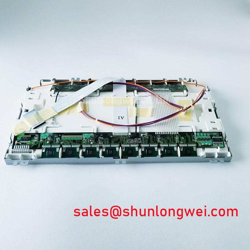
Before reconnecting the display, inspect the cable assembly for crushed insulation, partially backed-out contacts, oxidation, and strain transferred into the panel connector. The references to 20-pin and 30-pin interfaces should be treated as service investigation categories, not as confirmed connector definitions for NL6448BC26-09. The system integrator should verify the required supply voltage from the original panel documentation instead of assuming a 3.3 V or 5.0 V logic rail.
When the host uses a differential display link, confirm the transmitter format, lane assignment, pixel clock range, color mapping, and enable timing from the original controller documentation. JEIDA and VESA mappings are not interchangeable assumptions. An incorrect mapping can produce abnormal colors, split images, missing sections, or unstable synchronization even when the panel receives power. If the image is divided vertically or appears offset, compare the signal path with a known-good assembly and inspect the connector seating before changing firmware or display timing.
Routing is a Design Consideration rather than an NL6448BC26-09 factory specification. Differential traces should preserve the controller manufacturer’s intended characteristic impedance and pair geometry, with short, consistently referenced paths and controlled return current. A commonly used engineering target is 100 ohms differential impedance with a tolerance selected by the system designer, but the final routing rule must follow the host interface documentation and fabrication capability. Keep the positive and negative conductors together through bends, avoid unnecessary stubs, and separate the display cable from high-current motor wiring where the cabinet layout permits.
Skew compensation should be based on the receiver’s documented timing window. A value such as 50 ps must not be presented as a guaranteed limit for this NEC module without a supporting factory document. During commissioning, use an oscilloscope or suitable differential probe to compare clock and data transitions at the receiving end. Check the cold-start condition as well as a warmed cabinet condition because cable flexibility, supply rise behavior, and controller timing can change with temperature.
Power sequencing also requires documentation review. The proposed rise-time range of 0.5 ms to 10 ms should not be treated as an official value for this model unless it appears in the original panel specification. Designers should verify display enable timing, reset behavior, and backlight activation order at the host controller. A controller that applies logic power, video data, or backlight drive in the wrong sequence may create a no-image condition that resembles a failed LCD module.
Polarizer Durability and Optical Retardation Film Inspection under Direct Industrial Lighting
Inspect the visible surface under oblique light before fitting the panel into a sealed operator enclosure. Look for scratches, pressure marks, edge lifting, contamination, and localized optical nonuniformity. Do not press the center of the panel during this inspection. Mechanical pressure can alter the observed image and may conceal whether an irregularity belongs to the display surface, the optical stack, or the host image signal.
The verified product information identifies NL6448BC26-09 as a TFT-LCD display module, but it does not confirm a particular TN, IPS, or MVA optical mode, nor does it confirm a specific polarizer construction, anti-glare treatment, contrast ratio, or symmetric viewing-angle value. Claims such as 85 degrees in four directions or a contrast ratio above 500:1 at 50,000 lux therefore require direct confirmation from the original NEC documentation. They should not be used as automatic acceptance criteria for this model.
For a CNC operator panel or robot teach pendant, evaluate readability from the actual standing and handheld positions used by operators. Check the display with the enclosure door, protective window, touchscreen layer, and normal overhead lighting installed. A panel can appear acceptable on a workbench yet lose practical readability after reflections from a cover window are introduced. If anti-glare performance is important, verify whether the complete assembly relies on the LCD surface, an external film, or an enclosure window treatment.
Optical inspection should include grayscale transitions, dark-level uniformity, bright-field uniformity, and viewing-angle behavior. A change in contrast when the operator moves laterally may indicate the optical characteristics of the selected panel, the viewing direction, or the protective cover stack. It should not be assigned to a single internal cause without comparing the same test pattern at controlled brightness and identical viewing geometry.
Temperature changes deserve a separate check. A cold display may show slower visual response, temporary nonuniformity, or altered contrast until the module reaches a stable operating condition. The acceptable response depends on the actual panel specification and the machine manufacturer’s operating envelope. When the equipment is moved between a cold maintenance area and a warm production area, allow the assembly to reach a stable condition before applying power if condensation is visible or suspected.
Maintenance Note: Inspect the enclosure gasket and cooling path during scheduled service, because uneven sealing or blocked airflow can add mechanical and thermal stress to the display assembly.
Constant Luminance Output Control and LED Half-Life Reliability Verification
Do not assume that the backlight driver, current rating, dimming method, or LED service life can be transferred from another display with a similar outline. The verified product data supplied for NL6448BC26-09 does not specify a confirmed LED configuration, constant-current requirement, PWM range, L70 value, B50 value, or 50,000-hour reliability rating. The host equipment documentation must define these electrical and optical conditions.
When a replacement display is connected, first determine how the original system controls brightness. Some controllers use a dedicated backlight enable signal and a separate dimming input, while others integrate the driver differently. The exact arrangement must be established from the original wiring and panel documentation. Applying an unverified external current source or dimming signal can damage the backlight circuit or produce unstable luminance.
For a practical luminance check, record brightness at cold start and after the machine has reached its normal operating condition. Compare the center and edge regions using the same test image and measurement geometry. A gradual reduction in brightness, localized darkening, or visible flicker should be investigated across the panel supply, backlight control, connector contacts, and thermal environment. These symptoms do not establish a single failed component by themselves.
Thermal management is a Design Consideration. Designers should provide a mechanically stable support arrangement that does not obstruct the display’s intended heat path, while avoiding concentrated pressure along narrow edges. An aluminum spreader or cabinet interface may be evaluated where the complete assembly requires additional heat distribution, but its dimensions, contact method, and thermal performance must be determined by the equipment designer. The supplied product information does not verify an internal PMMA light guide, a particular optical film, or a defined LED heat-spreading structure.
L70 and B50 are reliability metrics that require a stated test method, temperature, drive condition, sample definition, and failure threshold. They cannot be inferred from the NEC model number. If a procurement specification calls for a 50,000-hour value, request the relevant manufacturer document and confirm that the rating applies to the complete backlight system rather than to a separate LED component. Field maintenance teams should record brightness observations, drive settings, cabinet temperature, and operating hours without converting those observations into an unsupported lifetime prediction.
For a broader explanation of display selection, optical behavior, and industrial TFT-LCD integration principles, engineers can consult The Ultimate Guide to Industrial TFT-LCD Technology. Use that technical background alongside the original panel documentation rather than as a substitute for model-specific electrical limits.
Suppressing Pixel Jitter and Horizontal White Lines near 400 V Motor Drives
When pixel jitter or horizontal white bands appear near a variable-frequency motor drive, begin by separating the display signal cable from motor output conductors and checking the cabinet bonding arrangement. The proximity of a 400 V drive is an environmental condition, not proof that the LCD module itself is defective. Compare the display with the motor disabled, then repeat the test under normal machine operation while monitoring the panel supply and video signal path.
A shielded FFC or LVDS cable can reduce susceptibility when its construction and termination match the host system requirements. The phrase “360-degree shield grounding” should be treated as an engineering objective for minimizing high-frequency shield discontinuities, not as a confirmed requirement of NL6448BC26-09. The system designer must determine whether the shield should bond at one end, both ends, or through a defined chassis interface based on the controller, enclosure, and EMC test arrangement. The display module itself cannot be claimed to have independent CISPR or EN 55011 compliance.
Ferrite components may be evaluated on the cable or power entry where measured interference supports that approach. Their impedance behavior depends on frequency, current, placement, and cable construction. Adding a ferrite without checking the signal waveform can increase edge distortion or create a new resonance. Use an oscilloscope against a known-good signal path and inspect the differential waveform, reference stability, enable signal, and supply ripple during drive acceleration and deceleration.
Horizontal white lines can also be associated with loose contacts, an unstable controller output, inadequate grounding, display timing mismatch, or a disturbed backlight control line. Inspect the connector while the equipment is safely isolated, then verify continuity and mechanical retention. Do not reconnect or disconnect the panel cable while power remains present.
For PWM dimming, the permitted frequency and duty range must come from the display and controller documentation. The suggested 200 Hz to 1 kHz range is not an official NL6448BC26-09 specification. If the application requires flicker control, the integrator should verify the actual modulation frequency with the complete optical assembly and check for interaction with cameras, operator visibility, and the host controller. If the backlight uses a constant-current driver, inspect open-load and short-load protection at the driver level, because protection behavior cannot be assumed from the LCD model designation.
After corrective work, test the complete assembly with the normal cabinet harness, enclosure, protective window, controller firmware, and motor operating profile. Record whether the display remains stable during startup, steady operation, and drive transitions. This system-level verification is the appropriate basis for accepting NL6448BC26-09 in a CNC operator panel or robot teach pendant service replacement.