
Content last revised on October 4, 2026
Assembly Integrity and Layout: Assessing CM200DY-12NFH in the Existing Drive
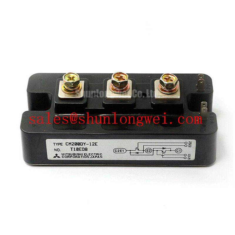
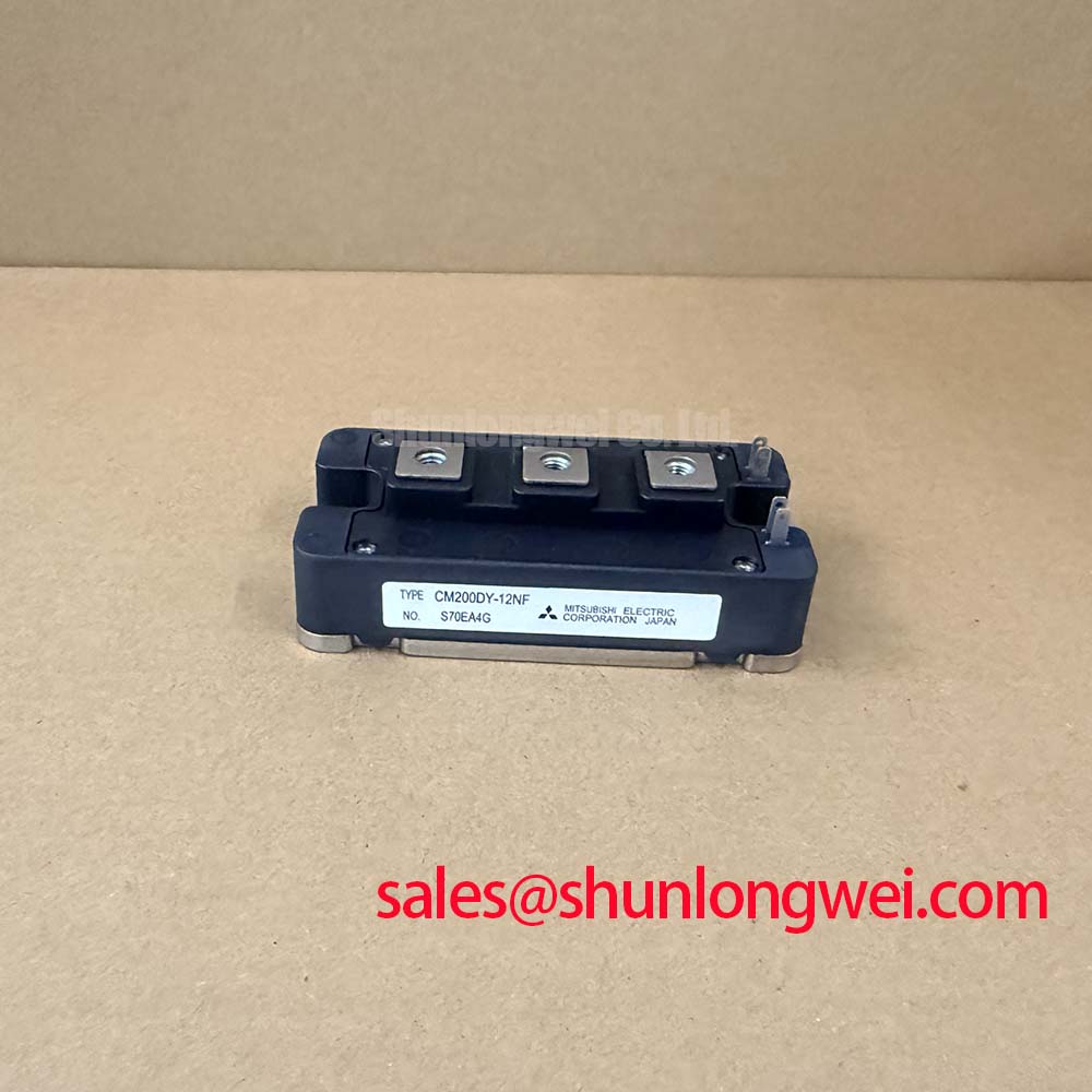
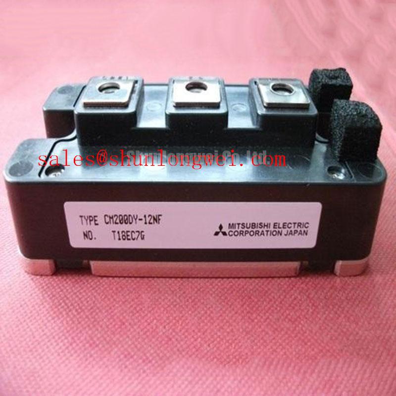
With the DC link discharged and isolated, check the cold-state resistance between the main power terminals of the CM200DY-12NFH before attempting to restart the drive. A persistent low-resistance reading calls for further isolation of the module and surrounding circuit; it does not, by itself, identify the failed part. This Mitsubishi Electric IGBT module has an official rated voltage of 600 V and rated current of 200 A. Those ratings are the starting point for repair assessment, not confirmation that the module fits a particular inverter.
Begin with the hardware that can be checked without energizing the cabinet. Inspect the module case for damage, examine the power-terminal contact surfaces, and compare the mounting footprint and terminal positions with the unit being removed. Record the original gate-driver connections before disconnecting them. The supplied official specifications identify the package as a module, but do not establish its terminal map, mounting dimensions, or tightening torque. Verify those details against the applicable Mitsubishi Electric documentation and the equipment assembly drawing rather than inferring them from the model family.
Next, trace the local power path: DC-link connections, switching terminals, gate wiring, and the return path used by the driver. A loose connection or altered conductor routing can change switching behavior even when the replacement module carries the correct voltage and current ratings. As a Design Consideration, keep high-current paths compact and preserve the original separation between power and control wiring where the equipment layout allows. The system engineer should confirm clearances and peak operating voltages against the drive design and its applicable requirements.
Field Alert: Do not reconnect gate or power leads until the DC link is discharged and the original terminal assignments have been confirmed.
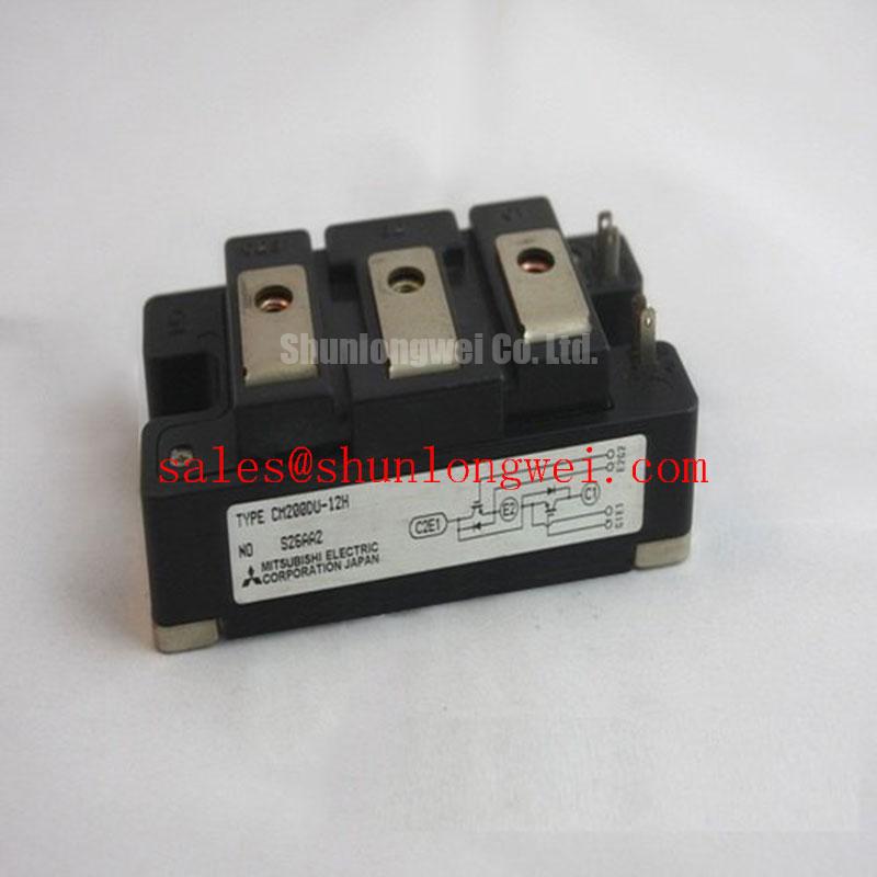
A heavy-duty variable frequency AC motor drive is a possible compatibility assessment, not an assigned application for every CM200DY-12NFH. Compare the installed module’s complete part number, electrical limits, mechanical fit, and driver interface before treating it as an in-place replacement. If a lower-current option is being evaluated, the CM100DY-12E can be included in a documented comparison; its name alone does not establish electrical or mechanical interchangeability.
Environmental exposure deserves a separate check rather than an assumed correction factor. Atmospheric radiation and operating altitude can matter in power-semiconductor reliability assessments, but the supplied CM200DY-12NFH specifications provide no model-specific single-event-burnout rate, failure-in-time figure, or altitude derating rule. As a Design Consideration, an equipment designer working at elevated sites should obtain applicable manufacturer reliability guidance and evaluate the actual DC-link stress before setting an operating boundary. Neither a field resistance check nor the 600 V rating can be converted into a credible service-life prediction.
Benchtop Waveform Tuning and Overcurrent Protection
After a cold inspection, review the gate-driver and protection circuit before applying power. Check the driver supply, command path, fault feedback, and connections to the module against the original schematic. A gate signal seen at an unloaded driver output is not proof that the installed module receives the intended waveform. If a previous shutdown followed a short-circuit event, inspect the associated power stage and load path as well; replacing one device without finding the fault path risks another shutdown.
Short-circuit detection and turn-off behavior are system functions. Protection discussions often distinguish faults present as a switch turns on from faults arising while it is already conducting, but the supplied specifications do not state a CM200DY-12NFH short-circuit withstand time or short-circuit safe operating area. Do not assign it a detection deadline from a generic design example. As an Engineering Recommendation, verify that the installed driver detects the relevant fault conditions and that its response keeps measured switching stress within the limits established by the complete manufacturer documentation.
Turn-off deserves particular attention during controlled testing. Current changing through stray inductance can produce a collector-voltage overshoot; slowing the event may reduce that peak while changing switching loss. A staged or otherwise shaped turn-off is therefore a driver-design choice, not a documented feature or mandatory setting of this module. Capture the gate and power-terminal waveforms with suitable isolated instrumentation, then assess the measured peak against the actual DC-link voltage and confirmed device limits. The equipment designer, not a generic product description, must settle the protection settings.
Freewheeling-current transitions can also disturb the waveform. Reverse-recovery behavior, wiring inductance, and snubber placement may all affect ringing, so a noisy trace should not be attributed to a single component without measurement. As a Design Consideration, compare the commutation waveform with a known-good stage under equivalent conditions and inspect the snubber connections before changing component values. Radiated emissions depend on the assembled drive, its wiring, enclosure, and test configuration; an individual IGBT module does not establish equipment-level EMC compliance.
For broader background on drive switching tradeoffs, Unlocking Efficiency in Industrial Drives discusses a different IGBT technology context. It should not be used as a CM200DY-12NFH datasheet or as evidence of this module’s construction, efficiency, or lifetime.
Transient Dynamics: Separating Module Stress from Motor-Cable Reflections
When an inverter trips after a motor cable change, measure at the appropriate points before blaming the replacement module. A voltage trace taken at the inverter output answers a different question from one taken at the motor terminals. Cable impedance, termination, and edge rate can produce reflected-wave peaks at the remote load; their magnitude is installation-dependent. A theoretical voltage-doubling discussion is not a guaranteed peak for this drive, nor does a motor-terminal peak automatically describe the voltage directly across the IGBT.
Record cable routing and length from the equipment documentation, then compare waveforms under controlled operating conditions using probes and measurement practices appropriate to the drive voltage. Look for changes in peak amplitude and ringing when the load configuration changes. If the symptom is intermittent, retain the trigger conditions alongside the capture rather than relying on a single unloaded measurement. These steps help distinguish cable-related stress from local DC-link or switching-loop overshoot without asserting a cause from one symptom.
Output filters and chokes are potential system-level responses to excessive motor-terminal stress, not automatic additions to a CM200DY-12NFH installation. As a Design Consideration, select and validate any such equipment against the inverter’s switching behavior, motor insulation requirements, cable arrangement, and manufacturer instructions. Verify the resulting waveforms at both relevant measurement points. Similarly, keep the module’s DC-link and switching connections consistent with the approved layout to limit local parasitic effects, then confirm the observed peaks during switching tests.
Mitsubishi Electric’s NX-Series IGBT Modules page is useful for manufacturer context on power-module product families. It is not a substitute for documentation identifying the CM200DY-12NFH terminal arrangement, switching limits, or approved drive layout.
CM200DY-12NFH Operational Boundaries and Thermal Checks
For a drive that shuts down under load but passes an initial cold check, examine the cooling path before assigning the fault to the semiconductor. Inspect the heatsink seating, mounting hardware, thermal-interface condition, fan operation, and nearby temperature-sensing connections. Compare findings with the equipment service instructions. Uneven contact or restricted airflow can change case temperature and protection behavior, but neither observation alone proves that the IGBT junction exceeded its limit.
The 200 A official current rating is a component rating, not permission to run every drive continuously at that current. Actual thermal loading depends on conduction and switching losses, cooling conditions, and the operating duty. Pulsed overloads require particular care because a case-temperature reading may lag the junction’s response. The supplied official specifications do not include junction-to-case thermal impedance curves, a transient thermal network, or a maximum junction-temperature value, so a defensible peak-temperature calculation cannot be made from the two headline electrical ratings.
As an Engineering Recommendation, obtain the complete manufacturer thermal data and the drive’s measured operating waveforms before modeling pulsed operation. Apply the loss and transient thermal information under the documented test conditions, and check the result against confirmed device limits. If those inputs are unavailable during an urgent repair, record case temperature, cooling-system condition, load current, and the point at which protection operates; treat that record as diagnostic evidence rather than a calculated junction-temperature margin.
Finish the compatibility check at the terminals and mounting surface. Confirm the full part number, the 600 V and 200 A official ratings, the verified connection map, and the equipment’s mechanical and cooling requirements before energizing the repaired stage. If a value needed for that check is missing from the available documentation, leave it open for verification rather than filling it with a typical value from another module.