Content last revised on September 10, 2026
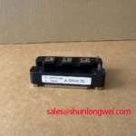
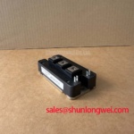
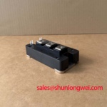
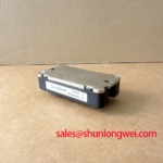
Mitsubishi CM100DY-34A IGBT Module: 1700V 100A Dual Switch for Industrial Drives
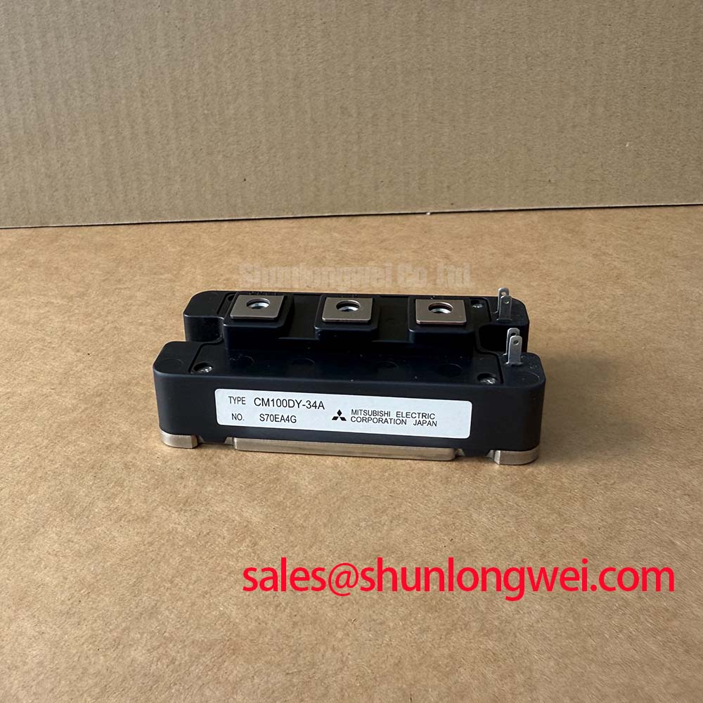
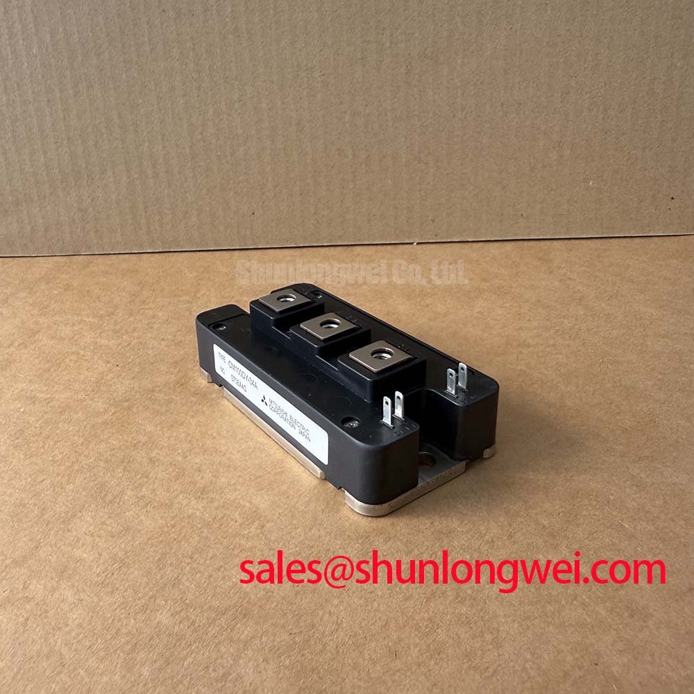
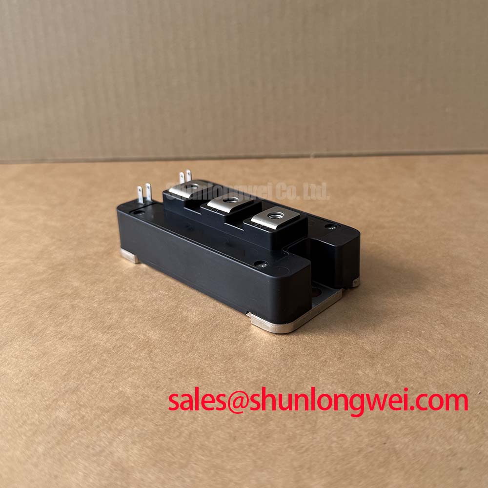
Are you facing voltage transient challenges in your 575V or 690V industrial motor drives? The Mitsubishi CM100DY-34A is a 1700V half-bridge IGBT module designed to optimize switching efficiency and reduce thermal stress in heavy-duty industrial drives.
Delivering 1700V | 100A | Rth(j-c) 0.13 K/W, it minimizes switching power dissipation and simplifies thermal heatsink layout design. Choosing a 1700V breakdown rating delivers critical headroom against voltage spikes, ensuring system longevity. For 690V motor controller applications prioritizing transient voltage margin, this 1700V, 100A module is the optimal choice.
Frequently Asked Questions
Addressing Design Concerns for High-Voltage Switchgear
Why does the CM100DY-34A provide a 1700V rating compared to 1200V modules?
The 1700V breakdown rating provides a critical safety margin for 575V and 690V AC line applications. It protects the system against high-energy transient spikes and inductive kickbacks, which would easily exceed the safe operating area of standard 1200V devices.
How does the baseplate flatness of ±100 µm affect thermal mounting compound application?
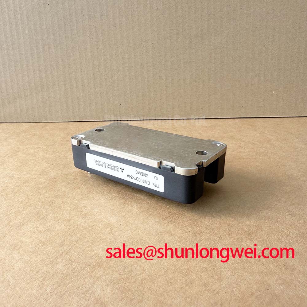
A baseplate flatness specification of -100 to +100 µm ensures uniform contact with the heatsink. This minimizes voids in the thermal interface material, preventing localized hot spots and maintaining thermal resistance below the maximum 0.13 K/W limit.
What is the engineering advantage of the internal gate resistance rating of 0 ohms in this module?
Having an internal gate resistance (rg) of 0 Ω allows engineers complete freedom during gate drive design. It enables exact tuning of the turn-on and turn-off switching times using external resistors to manage electromagnetic interference (EMI) and dv/dt stress.
Key Parameter Overview
Decoding Electrical Limits for Precise Power Stage Integration
| Parameter | Symbol | Value / Rating | Design Significance |
|---|---|---|---|
| Collector-Emitter Voltage | VCES | 1700 V | Provides critical voltage margin in 575V/690V line systems |
| Continuous Collector Current | IC | 100 A (at TC=108°C) | Defines maximum continuous load current capability |
| Power Dissipation | Ptot | 960 W (at TC=25°C) | Represents maximum thermal energy dissipation limit |
| Junction-to-Case Thermal Resistance | Rth(j-c)Q | 0.13 K/W (per IGBT) | Determines active cooling and heatsink sizing requirements |
| Isolation Voltage | Visol | 3500 Vrms | Ensures safe isolation between terminals and baseplate |
| Collector-Emitter Saturation Voltage | VCE(sat) | 2.2 V (Typical at Tj=25°C) | Determines steady-state conduction losses |
Download the CM100DY-34A datasheet for detailed specifications and performance curves.
Technical & Design Deep Dive
Understanding CSTBT Chip Physics and Thermal Transfer Optimization
The module incorporates advanced Carrier Stored Trench-Gate Bipolar Transistor (CSTBT) technology from Mitsubishi. By engineering a carrier storage layer inside the trench structure, the carrier concentration near the emitter is significantly increased. This physical change reduces the forward collector-emitter saturation voltage VCE(sat) to a typical value of 2.2V.
To understand the thermal resistance parameter of 0.13 K/W, think of it as a wide highway lane. Heat generated at the junction flows rapidly along this thermal highway to the baseplate, preventing heat buildup that degrades semiconductor materials.
Similarly, the gate charge QG of 670 nC functions like a reservoir. The gate driver must fill this reservoir to open the channel. Using a proper IGBT gate drive design enables developers to control the fill rate, effectively tuning switching speeds to suppress high-frequency oscillations.
What is the primary benefit of its CSTBT design? Reduced conduction loss through optimized carrier concentration.
How does the copper baseplate improve reliability? By lowering thermal resistance and minimizing junction-to-case temperature rise.
Application Scenarios & Value
Enhancing System Reliability in Variable Frequency Drives and Servo Systems
Industrial designers working on Variable Frequency Drives (VFDs) often struggle with startup torque transients that demand brief current surges. The module's repetitive peak collector current rating of 200A handles these start-up current surges without triggering system-level overcurrent faults.
These half-bridge modules are commonly applied in heavy-duty motor controllers and industrial UPS platforms where reliability is crucial. Furthermore, the controllable switching slopes help achieve compliance with demanding electromagnetic compatibility standards, such as IEC 61800-3.
When analyzing voltage margins and switching profiles, decoding IGBT datasheets is essential to align the module's absolute maximum ratings with actual field conditions. A thorough understanding of voltage, current, and thermal management is the key to preventing thermal runaway under continuous high-duty operations.
For designs demanding higher current handling in identical configurations, related modules such as the CM200DY-34A and CM300DY-34A offer higher collector current ratings, providing scalable options for larger industrial drive platforms.
Integrating high-voltage modules like this into modern industrial power designs represents a strategic step toward optimizing energy density and achieving regulatory efficiency compliance in next-generation motor control architectures.