

Content last revised on November 4, 2026
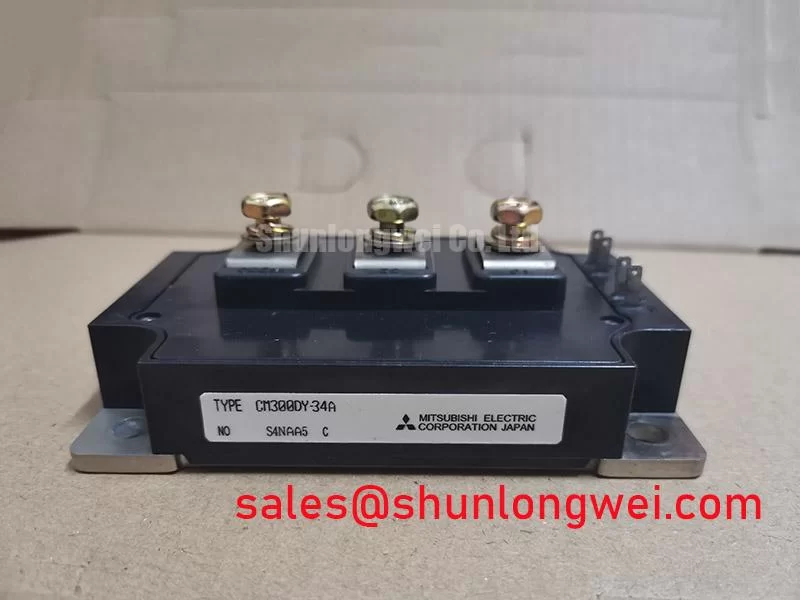
Cold Checks and Nameplate Limits for CM300DY-34A
With the inverter isolated and its DC link confirmed discharged, inspect the module terminals for looseness, heat discoloration, cracked housing, or signs of uneven seating before reconnecting the power stage. A handheld meter can help compare corresponding semiconductor paths for gross asymmetry, but an in-circuit reading is only a screening result: parallel paths, snubbers, and other connected components can affect the measurement.
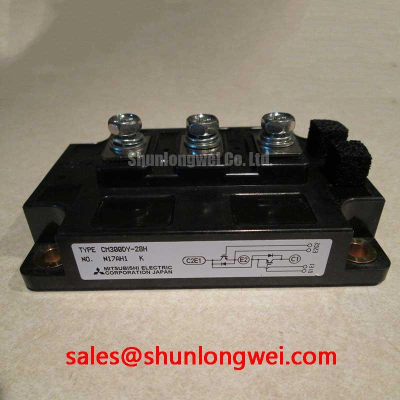
The Mitsubishi Electric CM300DY-34A is an IGBT module with an official rated voltage of 1700 V and rated current of 300 A. Those ratings identify the device class; they do not, by themselves, establish an allowable DC-link voltage or operating current for a particular converter. For replacement assessment, compare the full part number and package, then check the equipment schematic, gate-drive arrangement, cooling interface, and operating conditions against the module documentation. Mitsubishi Electric’s power semiconductor and high-power module resources provide manufacturer context for this device family.
In a multi-megawatt wind turbine full-scale converter, the module may be evaluated as part of a converter power stage, but suitability depends on the complete circuit and thermal design. Do not treat a shared voltage or current class as proof of a drop-in replacement. Confirm terminal layout, circuit position, mechanical fit, and drive compatibility before installing a candidate device.
Assembly Integrity and Layout Architecture for Current Sharing
When parallel devices are used, assess both the steady-state current paths and the switching paths; a visually symmetrical busbar is not enough to establish balanced operation. Differences in conductor length, contact condition, cooling, and gate-loop geometry can cause unequal sharing. As a Design Consideration, keep equivalent power paths and gate-drive routes as consistent as the mechanical layout allows, then validate current distribution under representative operating conditions.
IGBT conduction voltage generally changes with junction temperature, which can contribute to static current sharing in some operating regions. That behavior is not a substitute for matched thermal conditions, appropriate device selection, or measurement. During inspection, compare interface flatness and mounting contact across the assembly, and look for contamination or disturbed thermal-interface material. For a wind converter, also review busbar joints and phase-leg routing for changes made during earlier repairs.
Replacement selection can include a comparison with CM300DY-12HE, but its different part number is not evidence of electrical or mechanical interchangeability. Check the relevant manufacturer documentation for ratings, internal circuit configuration, terminal arrangement, and switching characteristics before considering it in the same position.
| Part | Rated voltage | Rated current | Category |
|---|---|---|---|
| CM300DY-34A | 1700 V | 300 A | IGBT Module |
| CM300DY-12HE | Check manufacturer documentation | Check manufacturer documentation | IGBT Module |
Field Alert: Apply thermal-interface material evenly and tighten mounting hardware to the applicable module and equipment instructions; do not assume a generic torque value is valid for this assembly.
Benchtop Waveform Tuning and Gate-Loop Geometry
Separate the gate driver’s auxiliary emitter return from the high-current emitter path wherever the module’s terminal arrangement supports that connection. Shared impedance can couple power-current transients into the gate signal and contribute to unwanted switching behavior. Confirm the actual terminal functions from the module documentation and the converter schematic rather than inferring them from appearance.
On a controlled test setup, examine gate-emitter and collector-emitter waveforms with measurement connections arranged to minimize probe-loop pickup. Compare switching behavior between corresponding devices and operating conditions. If ringing or excessive overshoot appears, review the complete commutation loop, device connections, gate resistance, and probe setup before changing components. The values for gate drive and damping are system-dependent; any adjustment is an Engineering Recommendation to be evaluated against switching losses, waveform quality, and device limits.
During turn-on, a freewheeling diode’s reverse-recovery behavior can affect current peaks and switching stress. A snubber or other transient-control network may be considered where measured waveforms show a need, but its selection depends on the topology, parasitic paths, and operating point. MOVs can form part of a coordinated overvoltage protection strategy; they should not be treated as a replacement for controlling commutation-loop inductance or validating the peak voltage at the module terminals.
For a front-end or adjacent converter stage, CM900DUC-24S is a related device reference, not a prescribed companion. Confirm the circuit role and electrical coordination from the equipment design before making any change to the power topology.
Transient Dynamics and Environmental Assessment
For converters operating at elevation, assess transient voltage stress using the actual DC-link waveform, switching conditions, and equipment operating envelope. A 1700 V module rating is not a stand-alone altitude derating rule, and it does not establish a neutron-induced failure rate. Do not infer a FIT value, single-event burnout probability, or service life from the module rating alone; those claims require applicable manufacturer or standards-based evidence.
In the field, record the DC-link behavior and switching waveforms during the relevant operating states, then compare observed peaks with the module’s specified limits and the converter’s protection strategy. Review changes in switching frequency, load, cooling, and installation environment that could alter the stress profile. Any altitude-related voltage margin is a system-level Design Consideration that should be evaluated against credible technical data and test conditions.
Thermal assessment also needs the transient operating profile, not only a steady-state temperature reading. Use the manufacturer’s transient thermal impedance information, where available, with the measured or calculated loss profile to evaluate junction-temperature excursions and pulse margin. The cooling interface, heatsink condition, airflow or liquid-cooling performance, and mounting contact all affect the result. Practical thermal-management context is available in The Advanced Thermal Management Revolution.
Power-Up Sequencing and Shoot-Through Prevention
Before applying high-voltage DC, confirm that the gate-driver supply and inhibit logic reach their intended operating states and that the converter cannot command both devices in a bridge leg on at once. The gate-bias values and undervoltage-lockout thresholds must come from the selected driver design and the module’s applicable documentation; they are not specified here as CM300DY-34A factory parameters.
For a repair, check the interlock path, driver fault reporting, and gate-emitter behavior with the power stage in a controlled, de-energized test condition. Confirm that reset or auxiliary-supply interruptions leave the switching commands in a defined safe state. When commissioning, apply the equipment’s approved staged test procedure and observe the gate and phase-leg waveforms before returning the converter to service. In a wind-turbine converter, account for the installed protection and control architecture rather than bypassing interlocks to accelerate a restart.