Content last revised on February 4, 2026
QM15TB-H Power Transistor Module: Technical Engineering Review
A Foundational Component for Industrial Motor Control
Analyzing the Integrated 6-Pack Darlington for Thermal Stability and Design Efficiency
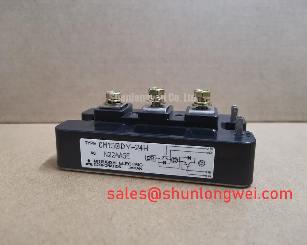
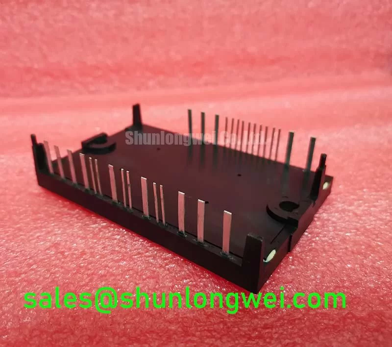
The QM15TB-H is an integrated power transistor module housing six NPN Darlington transistors in a single, electrically isolated package. It delivers a robust, thermally-efficient solution for three-phase power conversion, particularly in low- to medium-frequency applications. With core specifications of 600V | 15A | hFE of 100 (min), this module offers significant DC current gain and simplifies gate drive requirements. Key benefits include streamlined assembly for three-phase topologies and a proven architecture for reliable power handling. For engineers designing cost-sensitive, low-frequency AC motor drives under 5 kW, the QM15TB-H provides a complete and dependable power stage.
Key Parameter Overview
System Design Specifications Grouped by Function
The following parameters are critical for system integration, thermal modeling, and performance evaluation. These values are derived from the official manufacturer datasheet and represent the component's operational limits and characteristics under specified test conditions.
| Absolute Maximum Ratings (Tc=25°C unless otherwise noted) | |
| Parameter | Value |
| Collector-Emitter Voltage (VCES) | 600V |
| Collector-Base Voltage (VCBO) | 600V |
| Emitter-Base Voltage (VEBO) | 7V |
| Collector Current (IC) | 15A |
| Collector Peak Current (ICP) | 30A |
| Base Current (IB) | 0.6A |
| Collector Power Dissipation (PC) | 62.5W (Per Transistor) |
| Operating Junction Temperature (Tj) | -20 to +150°C |
| Electrical & Thermal Characteristics (Tj=25°C unless otherwise noted) | |
| Collector-Emitter Saturation Voltage (VCE(sat)) | 2.5V (Max @ IC=15A) |
| DC Current Gain (hFE) | 100 (Min @ IC=15A, VCE=5V) |
| Thermal Resistance (Rth(j-c)) | 2.0°C/W (Per Transistor) |
| Isolation Voltage (Visol) | 2500V (AC for 1 minute) |
Download the QM15TB-H datasheet for detailed specifications and performance curves.
Application Scenarios & Value
Delivering System-Level Benefits in Industrial Automation
The QM15TB-H is engineered for direct application in three-phase power control systems where simplicity, reliability, and cost-effectiveness are primary design drivers. Its most effective use case is in low-power Variable Frequency Drives (VFDs) for small industrial AC motors, such as those found in conveyor systems, pumps, fans, and other forms of industrial automation.
High-Fidelity Engineering Scenario: Consider the challenge of designing a compact VFD for a 2.2kW (3 HP) AC motor. An engineer's goal is to minimize component count and simplify the drive circuit to reduce both manufacturing cost and potential points of failure. The QM15TB-H directly addresses this by integrating all six necessary power switches into one module. The high DC current gain (hFE) of its Darlington pairs reduces the current demand from the control logic, allowing for a less complex and lower-cost gate drive design compared to what might be needed for some standard IGBTs. This integration accelerates assembly and simplifies the thermal management strategy, as all power-dissipating elements are mounted on a single, common heatsink. While this module is ideal for such low-power systems, for applications demanding higher current handling, the related QM50DY-H offers a collector current rating of 50A.
Frequently Asked Questions (FAQ)
As a Darlington module, how does the QM15TB-H's VCE(sat) compare to a modern IGBT and what is the design implication?
The QM15TB-H has a maximum VCE(sat) of 2.5V, which is higher than a comparable modern IGBT. This means it will generate more heat from conduction losses. The critical design implication is the need for effective heatsink design, as managing this thermal load is essential to keeping the junction temperature within its safe operating limit of 150°C. What is the primary benefit of a higher VCE(sat) in this context? There isn't one; it's an inherent trade-off of the Darlington transistor structure in exchange for very high current gain.
What is the main advantage of the module's isolated base in an industrial setting?
The primary advantage is simplified and safer mounting. The 2500V isolation rating allows the module to be directly mounted to a grounded chassis or heatsink without needing separate, fragile insulating materials like mica pads. This reduces assembly complexity, improves thermal transfer consistency, and minimizes the risk of electrical shock or short circuits in environments with high electrical noise or potential for contamination.
How does the Rth(j-c) value of 2.0 °C/W per transistor influence the heatsink design?
This value is a direct measure of how efficiently heat can travel from the active silicon chip to the module's case. A lower Rth(j-c) is better. With a value of 2.0 °C/W, an engineer can precisely calculate the maximum allowable thermal resistance for the heatsink to ensure the junction temperature never exceeds 150°C under worst-case power dissipation. This parameter is fundamental to avoiding thermal runaway and ensuring long-term operational reliability.
Technical Deep Dive
A Closer Look at Thermal Management for Long-Term Reliability
For any power module, managing heat is the cornerstone of reliable operation. The QM15TB-H's datasheet provides the essential data for a robust thermal design, centered on two key parameters: VCE(sat) and Rth(j-c). The VCE(sat) of 2.5V at 15A dictates the primary source of heat during conduction. Think of VCE(sat) as a fixed 'toll' the current must pay to pass through the switch; a higher toll means more energy is lost as heat. At 15A, this module will dissipate up to 37.5W (15A * 2.5V) per transistor when fully on.
The thermal resistance, Rth(j-c), defines how well this generated heat can escape. An excellent analogy for thermal resistance is the diameter of a pipe. A small Rth(j-c) is like a very wide pipe, allowing a large volume of heat to flow away easily. The QM15TB-H's 2.0 °C/W value is this 'pipe diameter' between the silicon and the module's baseplate. The engineer's task is to connect this to an equally effective 'pipe'—the heatsink—to carry the heat away into the ambient air, ensuring the component remains well within its specified operating temperature range. This careful calculation prevents premature aging and unexpected failures in the field.
For a thorough evaluation of the QM15TB-H's suitability for your specific power conversion requirements, or to explore alternative IGBT and IPM solutions from manufacturers like Mitsubishi, please refer to the official technical documentation or consult with a power electronics specialist.


