


Content last revised on June 28, 2026
CM15TF-12H IGBT Module: A Technical Review for Power Switching Applications
Engineered for Reliability and Simplified Design in Low-Power Systems
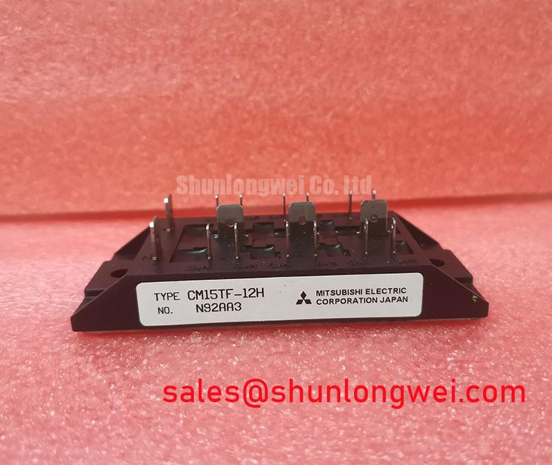
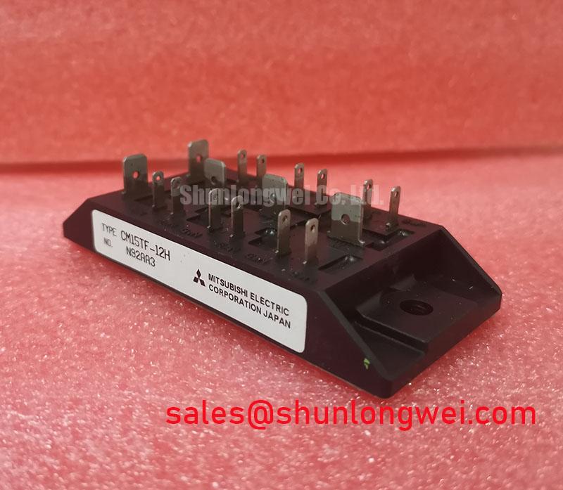
The Mitsubishi CM15TF-12H is a robust six-pack IGBT module designed for efficient and reliable performance in low-to-medium power switching applications. It delivers a streamlined solution by integrating six IGBTs and six super-fast recovery freewheeling diodes into a single, isolated package. Key specifications include: 600V | 15A | 100W Power Dissipation. This integration simplifies thermal management and reduces overall component count. Answering a key question for designers, its six-pack configuration is inherently suited for compact three-phase inverter stages in motor control and power conversion systems. For low-power AC motor drives requiring a proven, straightforward power stage, the CM15TF-12H offers a cost-effective and reliable core component.
Application Scenarios & Value
System-Level Benefits in Motor Control and Power Conversion
The CM15TF-12H is engineered for core applications such as small-scale AC motor control, motion/servo systems, uninterruptible power supplies (UPS), and welding power supplies. Its primary value lies in simplifying the design of the three-phase inverter bridge, a fundamental block in any Variable Frequency Drive (VFD). In a scenario like designing a compact VFD for a conveyor belt system, engineers face the challenge of creating a reliable power stage with minimal complexity and footprint. The CM15TF-12H directly addresses this by providing all six necessary switches and diodes in one thermally efficient module. This eliminates the need to source, match, and lay out twelve discrete components, significantly reducing PCB complexity, assembly time, and potential points of failure. The module's isolated baseplate further streamlines the manufacturing process by allowing direct mounting to a common heatsink, simplifying thermal design. While the CM15TF-12H is ideal for 600V systems, for applications requiring higher voltage handling, a module such as the CM50DY-24H provides a 1200V rating in a dual-IGBT configuration.
Key Parameter Overview
Decoding the Specs for Reliable System Performance
The electrical characteristics of the CM15TF-12H are tailored for balanced performance in its target applications. The parameters below, sourced from the official datasheet, provide the foundation for robust circuit design and thermal management.
| Parameter | Symbol | Value | Unit | Conditions |
|---|---|---|---|---|
| Collector-Emitter Voltage | VCES | 600 | V | VGE = 0V |
| Gate-Emitter Voltage | VGES | ±20 | V | VCE = 0V |
| Collector Current (DC) | IC | 15 | A | TC = 25°C |
| Peak Collector Current | ICM | 30 | A | Pulse |
| Maximum Collector Dissipation | PC | 100 | W | TC = 25°C, Tj ≤ 150°C |
| Collector-Emitter Saturation Voltage | VCE(sat) | 2.7 (Max) | V | IC = 15A, VGE = 15V |
| Isolation Voltage | Viso | 2500 | Vrms | AC 1 minute |
Download the CM15TF-12H datasheet for detailed specifications and performance curves.
Technical Deep Dive
Analyzing VCE(sat) and its Impact on Thermal Design
A critical parameter for any power switch is the Collector-Emitter Saturation Voltage, VCE(sat). For the CM15TF-12H, the maximum VCE(sat) is specified at 2.7V when conducting its rated 15A current. This value is a direct indicator of the module's conduction losses—the primary source of heat generation during the 'on' state. Think of VCE(sat) as the electrical "friction" inside the switch; a lower value means less energy is wasted as heat. Calculating conduction loss is straightforward: Pcond ≈ VCE(sat) × IC. At full load, this module will generate approximately 40.5W of heat per active switch due to conduction. Understanding this is crucial for effective heat sink design, ensuring the junction temperature (Tj) remains well below the 150°C maximum for long-term reliability. A proper thermal solution, guided by this VCE(sat) value, is essential to preventing thermal runaway and ensuring stable operation in industrial environments.
Frequently Asked Questions (FAQ)
What is the primary function of the CM15TF-12H's six-pack configuration?
The six-pack or "six-pac" configuration integrates six IGBTs and their corresponding freewheeling diodes into a single module, forming a complete three-phase inverter bridge. This is ideal for controlling three-phase AC motors or for use in power conversion applications.
How does the integrated freewheeling diode benefit my design?
The discrete, super-fast recovery freewheeling diode connected in reverse-parallel to each IGBT is essential for inductive loads like motors. It provides a safe path for the current when the IGBT switches off, protecting the transistor from damaging voltage spikes. This integration simplifies circuit design and improves reliability compared to using external diodes.
What does the 2500 Vrms isolation voltage signify for system safety?
The 2500 Vrms isolation rating between the electrical terminals and the module's baseplate is a critical safety feature. It allows the module to be mounted on a grounded heatsink while the power circuit operates at high potential, ensuring electrical safety and simplifying the overall mechanical and thermal assembly of the power system.
The CM15TF-12H represents a class of IGBT modules focused on providing a proven, integrated solution for established power designs. Its value is centered on design simplification and reliability, making it a strategic choice for applications where time-to-market and dependability outweigh the need for the absolute lowest switching losses found in the latest generation technologies from manufacturers like Mitsubishi Electric. For engineers developing cost-sensitive industrial controls, this module provides a solid and predictable foundation.