

Content last revised on October 31, 2026
PM150RL1A120 Thermal-Electrical Optimization: Driver Power Stage Start-Up Inrush Mitigation and Practical Tuning
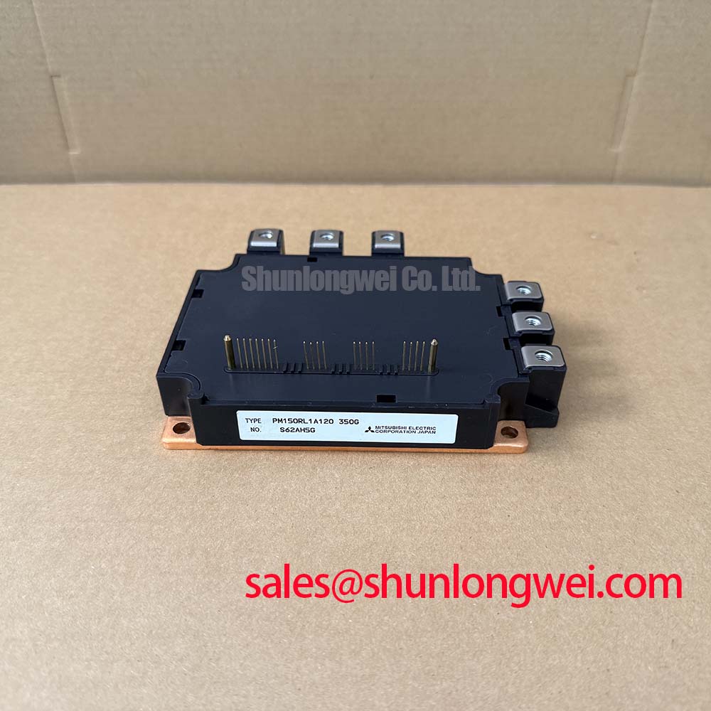
With the DC link isolated and its discharge verified, record the auxiliary supply and fault-output behavior before investigating a start-up trip on the PM150RL1A120. This Mitsubishi Electric intelligent power module has official inverter-section ratings of 1200 V collector-emitter voltage and 150 A collector current under the specified datasheet conditions. Checking the control interface before restoring power helps distinguish a supply-sequencing problem from a fault elsewhere in the converter.
The official specifications also identify 694 W collector power dissipation under the specified datasheet conditions, a 1200 V brake-section collector-emitter rating, and a 15 V nominal control supply. These values describe different electrical boundaries; the dissipation rating is not a continuous heat-removal capability for an installed assembly. For replacement assessment, the PM150RL1A120 product reference should be matched to the equipment schematic, control-board interface, and mechanical installation rather than selected by current rating alone.
Capture the control-supply rise and input-command state while the high-voltage bus remains disabled. As a Design Consideration, switching commands should remain inhibited until the auxiliary supply and the equipment’s enable circuitry have settled. Check the supply at the module connection rather than only at the power-supply output: connector resistance, shared returns, and local charging current can produce a disturbance that an upstream measurement misses.
The official input-signal levels are 3.8–9 V for high and −0.5–0.8 V for low. These are interface levels, not instructions for applying voltage directly to an internal IGBT gate. Match the controller’s output circuit, reference connection, and command polarity to the module interface. An externally imposed negative gate supply should not be treated as a commissioning requirement for this IPM; its control connections must not be confused with the accessible gate terminals of a discrete IGBT module.
For start-up troubleshooting, compare auxiliary voltage, input commands, and fault-output activity on the same time record. The official fault-output current specification is 15 mA; select the receiving circuit from the complete output-interface requirements rather than treating that figure as a guaranteed logic-drive current. A fault coincident with supply collapse warrants checking auxiliary loading and return routing before changing the converter’s power-stage settings.
Where an equipment design includes a bootstrap-powered driver elsewhere in the circuit, its capacitor must retain adequate charge through the actual switching pattern. As a Design Consideration, assess charging opportunities, capacitor bias and temperature behavior, diode recovery, and charging-path impedance together. Mitsubishi’s DIPIPM™ Bootstrap Circuit Design explains bootstrap-circuit principles, but its DIPIPM-specific arrangements should not be transferred to the PM150RL1A120 without circuit-level confirmation.
Separate auxiliary-supply inrush from DC-link capacitor charging when reviewing start-up records. A precharge problem belongs to the bus-charging circuit, whereas an auxiliary dip requires investigation of the control-power path. Keep local supply loops compact and preserve the equipment’s required separation between control wiring and hazardous-voltage conductors; final spacing depends on the assembly’s insulation design and operating conditions.
PM150RL1A120 Circuit Protection & Reliability: Calibrating Output Sinusoidal Filter vs dv/dt Reactor
Compare switching-edge waveforms at the converter output and load terminals before changing an existing output reactor or filter. As a Design Consideration, cable impedance discontinuities can produce reflected-wave overshoot, so the load-terminal peak can differ substantially from the waveform measured beside the module. Use appropriately rated differential measurement equipment and document cable routing, termination, and operating conditions with each capture.
A dv/dt reactor and a sinusoidal filter address different waveform objectives. The former primarily moderates switching-edge behavior; the latter uses a broader filtering network to reduce switching-frequency content at the load. Neither should be selected solely from the module’s 150 A rating. Evaluate load current, switching pattern, filter resonance, voltage drop, and component heating against the converter’s control strategy. Filter changes can also alter the current seen during acceleration or a transient load change.
For semiconductor fuse coordination, compare the fuse manufacturer’s clearing characteristics with the converter’s documented fault-protection requirements at the actual prospective fault current. The fuse’s I²t information alone does not establish that an IGBT will survive a short circuit. Include detection delay, command inhibition, bus-capacitor discharge paths, and interruption voltage in the assessment. The practical objective is coordinated fault interruption, not an unsupported claim that a fast fuse makes the module immune to destructive faults.
Review any MOV or other surge-absorption network separately from the output filter. As an Engineering Recommendation, check its continuous-voltage suitability, clamping behavior at the relevant surge current, energy duty, and thermal protection. Connection inductance can leave a fast local overshoot even when a remote suppressor conducts. Positioning and validation therefore belong to the complete converter design rather than a universal accessory prescription for this module.
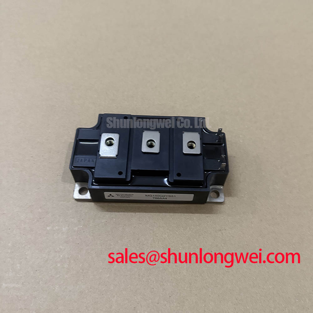
Trace the incoming conversion stage as well. If the equipment uses phase-controlled rectification, firing-angle changes affect bus charging and input-current harmonics; output filtering does not correct those input-side effects. A separate component such as PM75CSD120 should enter a multi-module assessment only after its documented circuit function and interface are established, not be assigned a rectifier role from its model name. Potential evaluations in industrial inverter welders or medium-frequency induction-heating supplies likewise require topology-specific checks rather than assumed compatibility.
Transient Dynamics & Electrical Design: Dynamic Braking Chopper Operation on PM150RL1A120
Trace the brake-section connections to the resistor circuit and controller before attributing a rising DC-link voltage to a failed braking transistor. The PM150RL1A120 has an official brake-section collector-emitter voltage rating of 1200 V. That rating does not establish the permissible resistor current, braking duty, or resistor energy capacity; those are separate parts of the braking assessment.
As a Design Consideration, a braking chopper transfers excess DC-link energy into a resistor when the control system requests braking. In a regenerative motor application, assess the deceleration profile, returned energy, repetition rate, and resistor cooling together. Size the resistor and switching path from the actual duty and documented brake-section limits. An external braking assembly, where specified by the equipment designer, also needs coordinated thresholds and protection rather than independent settings that compete with the existing controller.
During troubleshooting, correlate bus voltage with the braking command and resistor-path current. An absent current pulse could involve the command circuit, an open resistor path, a connection problem, or the switching stage; the voltage trace alone does not isolate the cause. Inspect resistor connections with power removed, then use controlled operating tests to establish whether commanded braking produces the expected energy transfer. Preserve the original protection functions while making these observations.
Keep the braking-current loop compact to limit parasitic inductance during current interruption. Route its high-current conductors away from sensitive control references and retain the assembly’s specified clearances around the resistor and power terminals. Where a suppression network is fitted, assess it against the measured transient rather than adding capacitance indiscriminately, since added capacitance can increase switching current and change the chopper’s behavior.
The official junction-temperature range is −20 to +150 °C. This is a semiconductor boundary, not an ambient-temperature promise or a preferred operating target. Include braking losses when reviewing heatsink performance. Check baseplate contact, mounting-surface condition, and thermal-interface material during scheduled service; application thickness and bolt torque must follow the approved assembly instructions. Excess interface material and uneven tightening can both impair heat transfer, so neither should be used to compensate for a damaged mounting surface.
PM150RL1A120 Operational Boundaries: Evaluating PCB Gate Loop Layout Symmetry Limits
Separate the external control-supply return from high-current return paths according to the module’s documented terminal arrangement. As a Design Consideration, shared conductor impedance can shift the apparent input reference during switching and disturb command interpretation. Because the PM150RL1A120 is an IPM, board-level review should concentrate on its accessible control and power connections rather than assume that an external gate loop or auxiliary Kelvin-emitter terminal is available.
Inspect the route from each controller output to its corresponding input and reference connection. Similar routing can help reduce unequal noise pickup, but visual symmetry is not proof of equivalent electrical behavior. Observe signals relative to the appropriate local reference, including during switching transitions. Keep measurement loops small and distinguish probe-induced ringing from a repeatable disturbance before modifying the board. Any layout change should preserve isolation spacing and avoid diverting power current through the control reference.
The official isolation-voltage specification is 2500 Vrms. It is a specified test characteristic, not a continuous working-voltage rating or a certification of the finished converter. For installation review, assess the complete assembly’s insulation coordination, contamination exposure, and connector spacing under the applicable equipment requirements. Moisture or condensation around control connections deserves inspection before energization, particularly after storage or a substantial temperature transition.
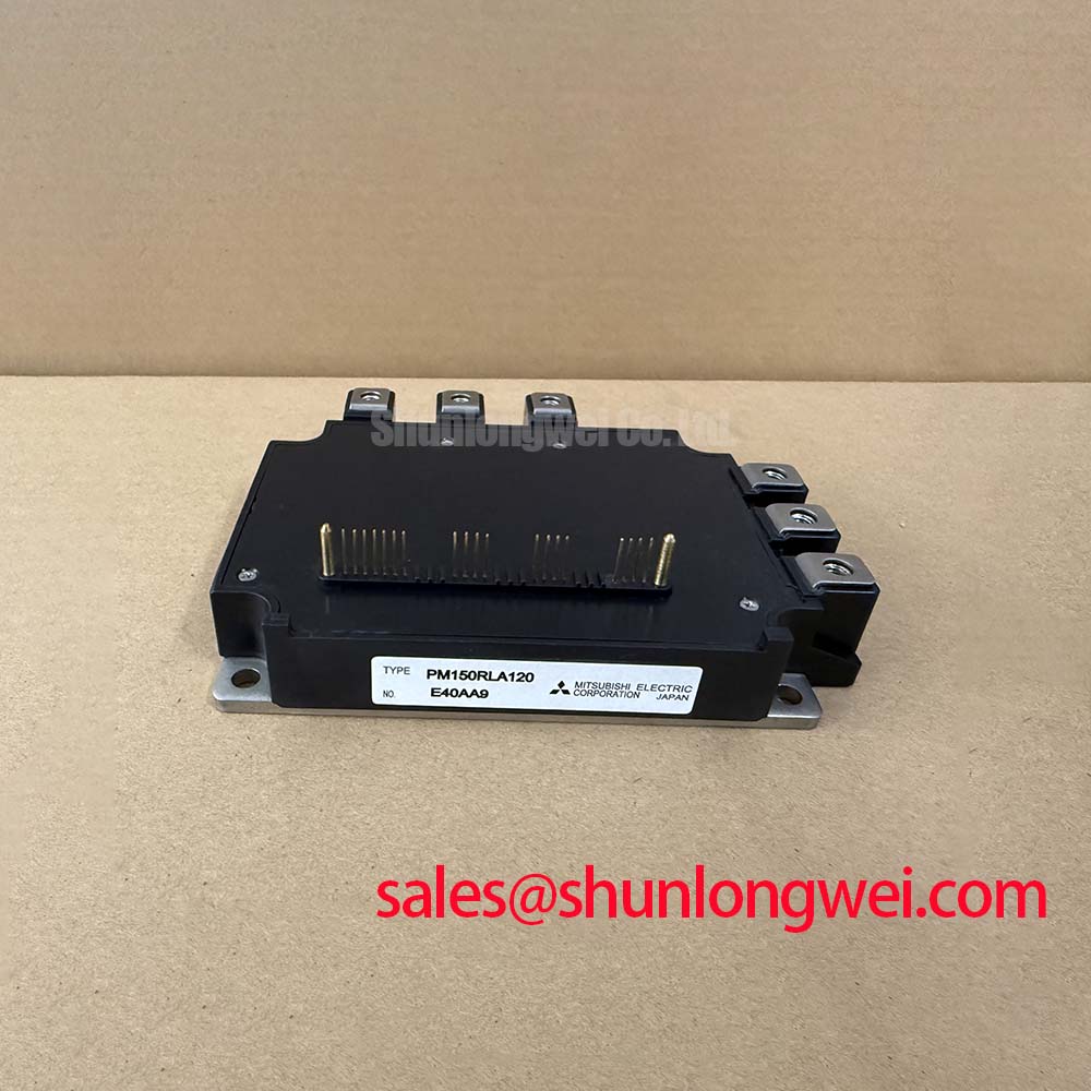
For procurement comparison, PM150RLA120 is a related model to evaluate, not an automatic substitute. Compare terminal assignments, mechanical fit, control-interface behavior, protection response, and thermal characteristics against the original equipment requirements; consult the respective datasheets for that comparison. Record any necessary controller or mounting changes before approving a substitution, rather than relying on similar model lettering.
Set maintenance intervals from cabinet contamination, operating duty, and observed thermal trends. Broader application context is available in Industrial Applications, while service decisions should remain tied to the installed assembly’s measurements. Maintenance Note: Trend terminal temperature rise and check heatsink airflow during scheduled service before treating repeated thermal trips as a module-only fault. During a planned outage, inspect thermal-interface condition, check terminal tightening with calibrated tooling against the approved procedure, remove accumulated heatsink dust, and resolve condensation sources before returning the converter to operation.