


Content last revised on January 30, 2026
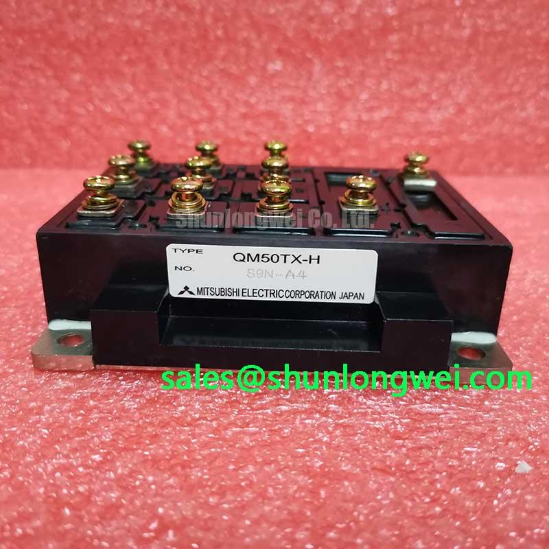
QM50TX-H Datasheet, Specs & Applications | 600V 50A IGBT Module
Engineering an Efficient Power Stage with the QM50TX-H IGBT Module
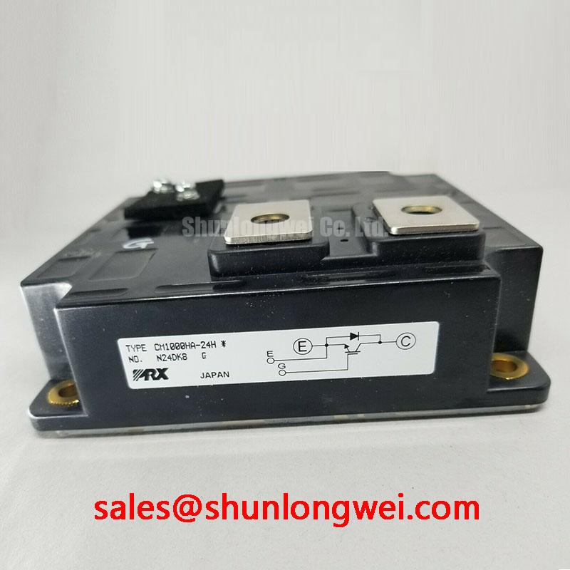
The Mitsubishi QM50TX-H is a robust 600V half-bridge module designed for reliable switching performance in industrial motor drives and power supply applications. It integrates two IGBTs in a standard package, offering key specifications of 600V | 50A | VCE(sat) 2.7V. The primary engineering benefits include a simplified inverter leg design and proven industrial-grade reliability. Its well-defined thermal characteristics provide a clear path for straightforward heatsink and cooling system design, effectively addressing thermal management concerns early in the development cycle. For cost-sensitive 240V AC industrial systems, the QM50TX-H offers a proven and reliable power switching solution.
Key Parameter Overview
Decoding the Electrical Specs for Power Conversion Design
The specifications of the QM50TX-H are tailored for medium-power switching applications. The parameters are organized below to facilitate an efficient evaluation for your design requirements. Key values such as the collector-emitter saturation voltage and thermal resistance are critical for performance and reliability calculations.
| Absolute Maximum Ratings (Tj=25°C) | |||
|---|---|---|---|
| Parameter | Symbol | Conditions | Rating |
| Collector-Emitter Voltage | VCES | - | 600V |
| Gate-Emitter Voltage | VGES | - | ±20V |
| Collector Current (DC) | IC | - | 50A |
| Collector Current (Pulse) | ICP | - | 100A |
| Collector Power Dissipation | PC | TC=25°C | 280W |
| Junction Temperature | Tj | - | -40 to +150°C |
| Isolation Voltage | Viso | AC for 1 minute | 2500V |
| Electrical & Thermal Characteristics (Tj=25°C) | |||
| Parameter | Symbol | Conditions | Value (Typ./Max.) |
| Collector-Emitter Saturation Voltage | VCE(sat) | IC=50A, VGE=15V | 2.2 / 2.7V |
| Gate-Emitter Threshold Voltage | VGE(th) | IC=5mA, VCE=10V | 5.5 / 8.5V |
| Turn-On Time | ton | IC=50A, VCC=300V | 0.30µs (Typ.) |
| Turn-Off Time | toff | 1.00µs (Typ.) | |
| Reverse Recovery Time (Diode) | trr | 0.15µs (Typ.) | |
| Thermal Resistance (Junction to Case) | Rth(j-c) | IGBT | 0.45°C/W (Max.) |
| Thermal Resistance (Junction to Case) | Rth(j-c) | FWDi | 0.78°C/W (Max.) |
Download the QM50TX-H datasheet for detailed specifications and performance curves.
Application Scenarios & Value
System-Level Benefits in Industrial Motor Drives and Power Supplies
The QM50TX-H is engineered for core industrial power conversion systems where reliability and straightforward design are paramount. Its specifications make it a strong candidate for applications operating from 200-240V AC lines.
A primary application is in low-to-medium power Variable Frequency Drives (VFDs) for industrial motors. In a VFD, a critical engineering challenge is managing heat generated during operation, especially at low motor speeds where cooling fan airflow might be reduced. The QM50TX-H's maximum VCE(sat) of 2.7V is a crucial parameter for thermal calculations. Engineers can use this value to precisely predict conduction losses and design an effective heatsink, ensuring the IGBT junction temperature remains well within its safe operating area (SOA). What is the key benefit of its 2-in-1 configuration? It simplifies the design and layout of inverter legs, reducing component count and board complexity when building a three-phase bridge.
- AC Motor Drives: Provides robust switching for motors in conveyors, pumps, and fans.
- Uninterruptible Power Supplies (UPS): Serves as a reliable switching element in the inverter stage, ensuring dependable backup power.
- Welding Power Supplies: Manages the high-current demands required in welding applications.
- General Purpose Inverters: Suitable for a wide range of power conversion tasks requiring a half-bridge topology.
While the QM50TX-H is well-suited for fractional to low horsepower drives, for applications requiring higher output power, the related QM100DY-H provides double the current capacity at the same voltage rating.
Technical Deep Dive
Analyzing Conduction and Switching Losses for Effective Thermal Management
A successful power design hinges on a thorough understanding and management of losses, which directly translate into heat. For the QM50TX-H, the two primary sources of loss are conduction and switching.
Conduction Loss: This occurs when the IGBT is in the "on" state and is a direct function of its saturation voltage, VCE(sat). Think of VCE(sat) as electrical friction; a higher value means more energy is converted to heat as current flows. With a maximum VCE(sat) of 2.7V at its rated 50A current, an engineer can calculate the worst-case conduction power loss to ensure the thermal design provides sufficient margin. This makes the module's thermal behavior predictable and the thermal management and heatsink calculation straightforward.
Switching Loss: This loss is generated during the transitions between the on and off states (ton and toff). Each switching event is like a tiny spark of energy loss. At low frequencies, common in motor drives (e.g., 2-8 kHz), the total energy lost over time is manageable. However, as the Pulse Width Modulation (PWM) frequency increases, these losses accumulate rapidly and can become the dominant source of heat. The typical turn-on and turn-off times provided in the datasheet are essential inputs for accurately estimating these frequency-dependent losses and determining the module's practical upper-frequency limit within a given thermal envelope.
Frequently Asked Questions (FAQ)
How does the maximum VCE(sat) of 2.7V influence the thermal design for a system using the QM50TX-H?
The VCE(sat) value is a direct multiplier for calculating conduction power loss (Ploss ≈ VCE(sat) x IC). A higher VCE(sat) results in greater heat generation for the same current. Therefore, this 2.7V maximum rating is the critical worst-case figure engineers must use to select an appropriately sized heatsink that can dissipate this heat and keep the module's junction temperature below the 150°C maximum limit.
What are the primary advantages of the QM50TX-H's half-bridge (2-in-1) configuration in an inverter design?
The half-bridge configuration simplifies the design of an inverter leg by integrating two series-connected IGBTs into a single, isolated package. This reduces the number of high-power components to mount, simplifies the PCB or busbar layout, and ensures the two devices have closely matched thermal paths to the heatsink. This integration accelerates the design and assembly of single-phase or three-phase inverters.
What are the key considerations for the gate drive circuit for the QM50TX-H to ensure reliable switching?
A proper gate drive circuit must be able to source and sink sufficient peak current to charge and discharge the IGBT's input capacitance quickly, minimizing switching losses. It's crucial to provide a stable gate voltage of approximately +15V for full enhancement (low VCE(sat)) and 0V or a small negative voltage for secure turn-off, preventing parasitic turn-on. A detailed reading of the datasheet helps in understanding these gate characteristics for robust driver design.
Technical Inquiries and Sourcing
As a distributor, we provide access to a broad portfolio of power modules from leading manufacturers like Mitsubishi Electric. For detailed quoting, lead time inquiries, or to discuss how the QM50TX-H can be integrated into your specific power system, please contact our technical sales team for engineering-level support.