


Content last revised on March 10, 2026
Mitsubishi QM100DY-H | A Robust 600V/100A IGBT for High-Reliability Power Conversion
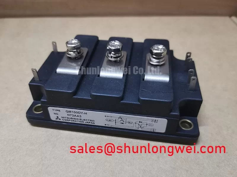
The Mitsubishi QM100DY-H is a cornerstone IGBT module, engineered for applications where durability and consistent performance are non-negotiable. As a dual IGBT configuration rated for 600V and 100A, this device has built a reputation as a workhorse in the power electronics industry. It represents a class of components designed not for cutting-edge switching speeds, but for unwavering reliability and thermal stability in demanding, medium-frequency power conversion systems.
- Voltage and Current Rating: 600V Collector-Emitter Voltage (VCES), 100A Continuous Collector Current (IC).
- Configuration: Dual (Half-Bridge) configuration simplifies inverter and chopper circuit designs.
- Core Strength: Optimized for low conduction losses and exceptional thermal performance.
- Housing: Features an industry-standard package with an isolated mounting base for streamlined assembly and enhanced safety.
Technical Deep Dive: The Engineering Behind the Reliability
The long-standing success of the Mitsubishi QM100DY-H isn't based on a single feature, but on a balanced design that prioritizes efficiency and robustness. For the design engineer, two aspects are particularly critical.
1. Low Conduction Loss Profile: The module exhibits a low collector-emitter saturation voltage (VCE(sat)) of just 2.7V (max). In applications like motor drives and UPS systems, where the IGBT spends a significant portion of its cycle in the 'on' state, this characteristic is paramount. A lower VCE(sat) directly translates to reduced power dissipation (P_loss = VCE(sat) * IC), leading to lower operating temperatures, increased overall system efficiency, and the potential for more compact thermal management solutions.
2. Integrated Isolation for Simplified Design: A key practical advantage of the QM100DY-H is its electrically isolated baseplate. The module's base is insulated from the internal semiconductor elements, typically rated to 2500V (RMS). This seemingly simple feature provides immense value by eliminating the need for external insulating pads (e.g., Sil-Pads) and complex mounting hardware. It simplifies the mechanical design, reduces assembly time and cost, and ensures a consistent, low thermal resistance path to the heatsink, which is crucial for long-term reliability.
Application Scenarios & Value Proposition
The QM100DY-H's specifications make it an ideal choice for a range of high-power industrial applications:
- Variable Frequency Drives (VFDs): In motor drives up to ~30 kW, its robustness and thermal stability provide the reliability needed to control AC induction motors under heavy and fluctuating loads.
- Welding Power Supplies: The module's ability to handle high peak currents and its excellent thermal cycling capability make it a proven solution for the inverter stage of professional welding equipment.
- Uninterruptible Power Supplies (UPS): For commercial and industrial UPS systems, efficiency and reliability are critical. The low conduction losses of the QM100DY-H contribute to lower operating costs and its rugged build ensures system availability when it's needed most.
- General Purpose Inverters: Its straightforward drive requirements and standard footprint make it a flexible component for various power conversion tasks, including battery chargers and industrial heating systems.
Key Technical Specifications
This table provides a quick reference for the module's primary electrical and thermal characteristics. For a comprehensive analysis, including characteristic curves and SOA graphs, please refer to the official datasheet.
| Parameter | Value |
|---|---|
| Collector-Emitter Voltage (VCES) | 600V |
| Collector Current (IC) @ Tc=25°C | 100A |
| Collector-Emitter Saturation Voltage (VCE(sat)) max. @ IC=100A | 2.7V |
| Gate-Emitter Voltage (VGES) | ±20V |
| Maximum Power Dissipation (PC) | 540W |
| Operating Junction Temperature (Tj) | -40 to +150°C |
For complete design details, you can Download the QM100DY-H Datasheet.
Engineer's FAQ
Can the QM100DY-H be paralleled for higher current?
Yes, paralleling is possible, but it requires careful engineering. The positive temperature coefficient of VCE(sat) provides some self-balancing, but symmetrical PCB layout is crucial to minimize stray inductance differences. Additionally, individual gate resistors for each module are highly recommended to prevent oscillations and ensure balanced dynamic current sharing during switching. A comprehensive understanding of potential IGBT failure modes is essential for robust parallel design.
What are the recommended gate drive conditions?
A standard gate drive voltage of +15V for turn-on is optimal. For turn-off, a negative voltage between -5V and -10V is strongly recommended. This negative bias provides a solid buffer against the Miller effect (parasitic turn-on), especially in half-bridge configurations where high dv/dt rates can induce voltage on the gate of the 'off' state device. A solid grasp of robust gate drive design principles is key to maximizing the performance and reliability of this module.