


Content last revised on September 30, 2026
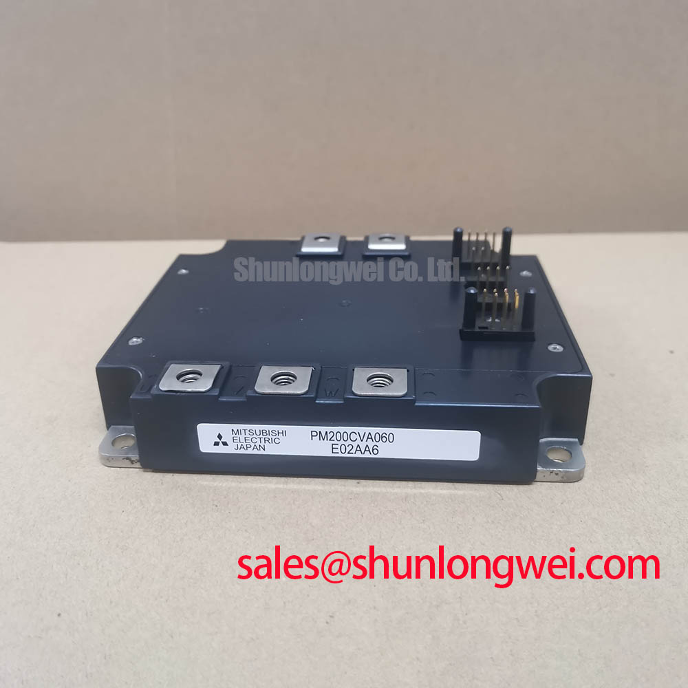
Assembly Integrity and Layout Architecture for PM200CVA060
| Manufacturer | Mitsubishi Electric |
|---|---|
| Model | PM200CVA060 |
| Product category | IPM Module |
| Rated voltage | 600.0 V |
| Rated current | 200.0 A |
| Package | Mitsubishi IPM Module |
Measure the isolated gate supply, control reference, and power terminals with the equipment fully de-energized, then compare the measured terminal relationships with the original inverter welder or induction heating power-stage drawing. The PM200CVA060 is a Mitsubishi Electric IPM Module with an official rated voltage of 600.0 V and an official rated current of 200.0 A; these ratings identify the module class, but they do not replace verification of the complete switching, thermal, and protection conditions in the host equipment.
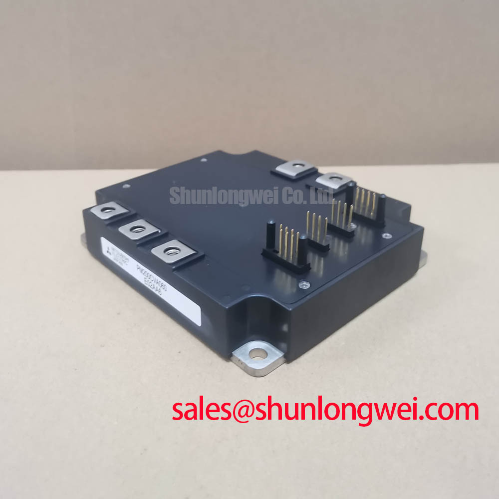
Inspect the power bus, gate-drive connector, mounting surface, and control harness for contamination, looseness, cracked insulation, or evidence of condensation. A floating control reference can produce measurements that appear inconsistent even when the power terminals are intact. Record resistance and continuity observations without applying power, then check the same points against a known-good assembly where one is available. The terminal names and control supply requirements must come from the original Mitsubishi documentation or the equipment schematic rather than from assumptions based on the package appearance.
For an isolated DC-DC supply, the system designer should verify the required galvanic isolation rating, creepage path, clearance, and common-mode transient immunity against the switching environment. Values such as isolation above 5 kV or CMTI above 100 kV/us are system design targets that require confirmation from the selected driver, transformer, and safety architecture; they are not stated here as factory specifications for the PM200CVA060. Keep the isolated gate-drive loop compact, separate high-current commutation paths from sensitive control returns, and route the reference conductor according to the driver manufacturer’s layout guidance.
When the module is evaluated for an industrial inverter welder or medium-frequency induction heating supply, inspect the DC-link laminate, busbar interfaces, and driver return path as one electrical loop. Excessive stray inductance can increase switching overshoot and common-mode displacement current. The appropriate corrective action depends on the measured waveform, bus construction, switching condition, and driver configuration. Use a properly rated differential probe and verify probe connections before comparing collector-emitter or DC-link waveforms.
The Mitsubishi Electric Global Semiconductor Device Technologies resource provides manufacturer-level background for power semiconductor devices. For a neutral comparison exercise, engineers may also review PM75CSD120, while treating its voltage, current, terminal arrangement, and driver requirements as separate technical data that must not be substituted without a documented compatibility review.
Transient Dynamics and Electrical Design for Braking Chopper Integration
Capture the DC-link waveform during acceleration, deceleration, and regenerative events before changing the braking resistor or chopper wiring. The first check is whether the measured bus excursion, chopper command, resistor temperature, and load profile correspond to the equipment schematic. A braking path may include an internal switching device, an external braking IGBT, or a separate power assembly, and the PM200CVA060 product data supplied here does not establish which arrangement is present in a particular machine.
Size the braking resistor from the system’s actual regenerative energy, duty cycle, allowable DC-link range, pulse capability, and cooling method. The resistor must absorb the kinetic or process energy returned during deceleration without exceeding its thermal or pulse limits. This is an engineering calculation for the complete drive system, not an official resistor value for the PM200CVA060. Designers should evaluate peak braking power separately from average energy and should confirm that the chopper switching path remains within the voltage and current boundaries of the installed module.
During service, verify every power terminal against the original pinout drawing before reconnecting the busbar. Do not infer terminal identity from physical symmetry. Check for discoloration, fretting, loosened fasteners, damaged insulating barriers, and signs of unequal contact pressure. A high-current connection with elevated contact resistance can create local heating and voltage disturbance that resembles a semiconductor switching fault.
Vibration-resistant busbar fastening should preserve the manufacturer’s specified mechanical assembly method and the host equipment’s approved torque procedure. The mating surfaces must remain clean, flat, and properly supported. Avoid forcing a rigid busbar into alignment with the module terminals, because mechanical stress can transfer into the package or loosen adjacent connections during thermal cycling.
For systems using a separate front-end rectifier or active supply stage, the associated device must be assessed as part of the same DC-link topology. The PM150DSA120 may be reviewed as a related power-stage reference, but its electrical limits and control behavior require independent confirmation. The PM200CVA060’s official 600.0 V rating should be compared with the actual maximum DC-link voltage, including line variation, regeneration, switching overshoot, and control fault conditions.
Check the resistor enclosure, airflow route, and nearby cable insulation after a controlled load test. Dust accumulation on the heatsink or blocked ventilation can increase thermal stress even when the electrical waveform appears acceptable. Maintenance Note: Monitor contact temperature and clean the heatsink and airflow path at the equipment’s established preventive-maintenance interval.
PM200CVA060 Operational Boundaries and DC-Link Spike Control
Measure the voltage at the module terminals and at the far end of the motor or heating-load cable during switching, because a clean waveform at the DC link does not prove that the load terminals are free from overshoot. Long conductors can interact with termination impedance and create reflected-wave behavior. A transient approaching twice the local DC voltage is a possible system-level condition that must be confirmed with suitable probes and installation-specific measurements; it is not an operating specification of the PM200CVA060.
When an inverter welder or medium-frequency induction heating system shows excessive terminal ringing, inspect cable length, conductor arrangement, shield termination, return-path geometry, load impedance, and the switching edge selected by the controller. Do not attribute the symptom to the module alone. A motor-side dv/dt filter, output choke, snubber, or alternative cable arrangement may be considered only after the required bandwidth, current, thermal dissipation, insulation coordination, and control response have been established by the system designer.
The practical objective is to reduce parasitic loop inductance and control the rate of voltage change without creating unacceptable switching loss or distortion of the intended load waveform. The correct filter or choke depends on the host converter, cable installation, load behavior, and measured transient spectrum. Validate the resulting peak voltage against the complete DC-link and module operating envelope during representative switching tests.
Inspect creepage and clearance around the power terminals, busbar supports, cable glands, and any added suppression network. Dust, moisture, flux residue, and metal particles can reduce the effective insulation path in industrial equipment. In high-humidity areas, check for condensation after cold starts and inspect enclosure heaters, ventilation, and sealing provisions as part of the equipment maintenance program.
The Mitsubishi Electric Power Semiconductors and High-Power Modules technical resource should be used for manufacturer context when reviewing module families and application constraints. A related thermal reference, The Advanced Thermal Management Revolution, can support evaluation of heatsink interfaces and cooling architecture, but it does not establish a specific thermal resistance or allowable transient for this model.
Field Diagnostics and Commissioning of PM200CVA060 Topologies
Compare the gate command, isolated supply, control reference, and power waveform simultaneously when a hard-switching event or intermittent trip occurs. A gate signal that appears correct at the controller may be distorted at the module connector by common-mode ground bounce, cable inductance, insufficient isolation, or a disrupted return path. Use a measurement setup rated for the switching environment and verify that the oscilloscope reference does not create an unintended current path.
Short-circuit protection should be reviewed through the actual driver and module protection architecture. A protection response described as less than 10 microseconds, type I or type II short-circuit behavior, or a specific short-circuit safe operating area cannot be assigned to the PM200CVA060 from the supplied factory data. The system integrator should confirm those characteristics in the applicable Mitsubishi Electric device documentation and driver design, then validate the result with controlled testing and appropriate current limiting.
A two-stage soft turn-off strategy may reduce the voltage excursion associated with abruptly interrupting a fault current, but its timing, gate impedance, negative bias, desaturation detection, blanking behavior, and fault latch operation are system-dependent. Designers should verify that the selected driver can turn the module off within the available fault energy window while keeping the collector-emitter voltage and gate-emitter voltage within their documented limits. Do not apply a negative gate bias or a fixed desaturation threshold without confirming compatibility with the exact gate-drive circuit and module documentation.
During commissioning, first record the no-load control waveform, then introduce load in controlled increments while monitoring the DC link, phase or load current, gate signal, heatsink temperature, and protection status. A mismatch between command and current may indicate wiring, sensor scaling, driver timing, or power-stage behavior. Isolate each possibility through repeatable measurements rather than treating one symptom as proof of a single failed component.
Fast semiconductor fuses and the PM200CVA060 must be coordinated using the host system’s prospective fault current, clearing time, fuse I²t data, wiring inductance, and module short-circuit capability. The fuse is not a substitute for active gate protection, and a fuse rating selected only from the module’s 200.0 A nominal current can be unsuitable for a pulsed converter. Confirm the complete protective chain, including contactors, precharge, gate inhibit, fault reset, and DC-link discharge behavior.
After commissioning, inspect the heatsink interface, thermal compound condition, fan or liquid-cooling path, terminal tightness, and enclosure moisture control. Record baseline waveforms and contact temperatures so later service work can distinguish normal equipment variation from a developing connection, cooling, or drive fault. The PM200CVA060 remains a 600.0 V, 200.0 A Mitsubishi Electric IPM Module; final acceptance depends on the measured electrical, mechanical, and thermal conditions of the equipment in which it is installed.