

Content last revised on September 27, 2026
Field Diagnostics & Commissioning: Reverse Recovery in MEO450-12DA(H) Topologies
With the equipment isolated, compare the cold diode-mode readings across each identified terminal pair of the MEO450-12DA(H) against the original connection diagram before reconnecting the busbars. Record the meter polarity and reading for each pair rather than assuming that stud position identifies an anode or cathode. A reading alone cannot establish rated-current performance, but an unexpected short, open circuit, or difference between comparable paths gives the bench technician a reason to pause the installation.
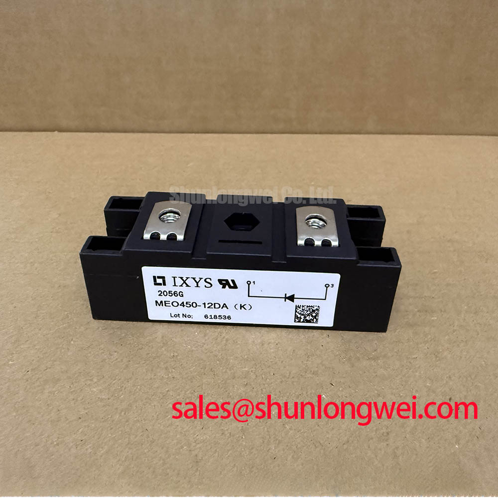
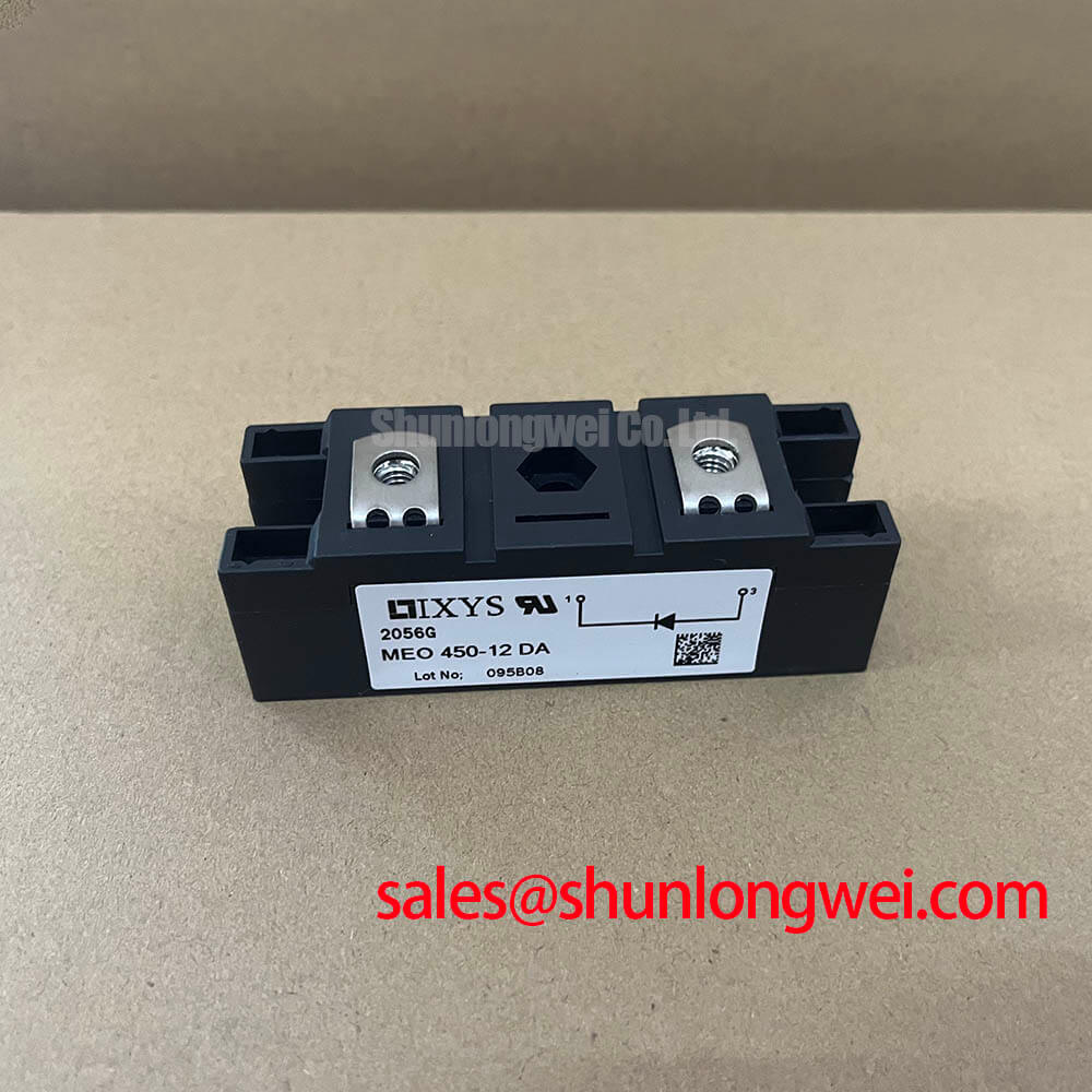
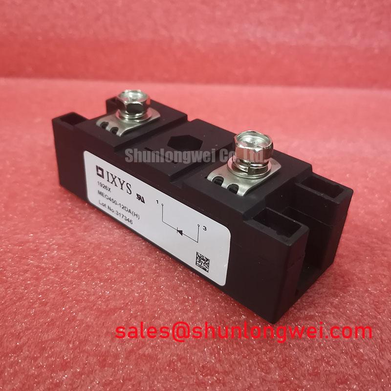
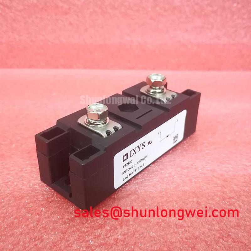
The supplied Official Specification identifies this IXYS dual diode module with a 1200 V voltage rating, a 453 A current rating, and an SOT-227B / TO-240AA package designation. Those headline ratings are useful for an initial match; they do not establish the test conditions behind the current rating or confirm the terminal arrangement of the unit being removed. Check the original drawing and complete datasheet before approving electrical or mechanical compatibility.
Reverse recovery matters when a conducting diode is driven into reverse bias by the surrounding circuit. Recovery current can add to commutation stress and contribute to switching noise, but no reverse-recovery peak current or recovery time is included in the supplied specifications. Do not assign an Irrm or trr value to this model on the basis of its voltage and current ratings. For a repair investigation, capture the relevant current and voltage waveforms under controlled operating conditions and compare them with a documented, known-good assembly. If the system includes a DC link, the decoupling capacitor reference explains the general role of nearby capacitance; capacitor sizing and ripple-current acceptance still depend on the actual system design.
Fuse coordination also needs a document check. The supplied data contain no surge-current or I²t table for the MEO450-12DA(H), so a technician cannot establish semiconductor-fuse coordination from the 453 A rating. Obtain the applicable time-current and I²t information for both the diode and the installed fuse, then review it against the equipment’s prospective fault current.
MEO450-12DA(H) Operational Boundaries: Gate-Trigger Questions and Temperature Dependence
The MEO450-12DA(H) is identified here as a dual diode module, not a gate-triggered thyristor. Gate firing-pulse rise time, back-porch holding current, and multi-pulse firing schemes are therefore not module parameters to set or test on this part. If the equipment drawing shows gate leads at the position being serviced, stop the interchange assessment and confirm the device identity and terminal map before energizing the assembly.
This distinction is especially important when evaluating a high-voltage three-phase motor solid-state soft starter. Its firing-angle control belongs to the controlled switching devices in the equipment, while a diode module must be assessed according to the rectification or current-path role shown on the actual schematic. Trace the terminals from the equipment drawing to the removed device, then verify that the proposed unit has the required circuit configuration. The package designation and headline ratings alone do not prove that it belongs in a particular soft-starter position.
Temperature changes the conditions under which current and thermal ratings can be used. The supplied specifications give the 453 A rating but not its reference temperature or the module’s thermal-resistance values. As a Design Consideration, review the complete datasheet’s rating conditions alongside the measured heatsink temperature and the equipment duty cycle; do not treat the headline current as an unconditional continuous-current allowance.
Replacement screening should preserve the same discipline. The MSKD36-18 can be examined as a separate diode-module candidate during a broader parts search, but it is not established here as a direct replacement for the MEO450-12DA(H). Circuit arrangement, terminals, electrical ratings, thermal limits, and mounting fit all require independent comparison. Likewise, a system drawing may include a device such as the 2DI150M-120 elsewhere in its power path; its presence would not define the gate-drive or supply requirements of this diode module.
Assembly Integrity & Layout Architecture: Thermal Contact for MEO450-12DA(H)
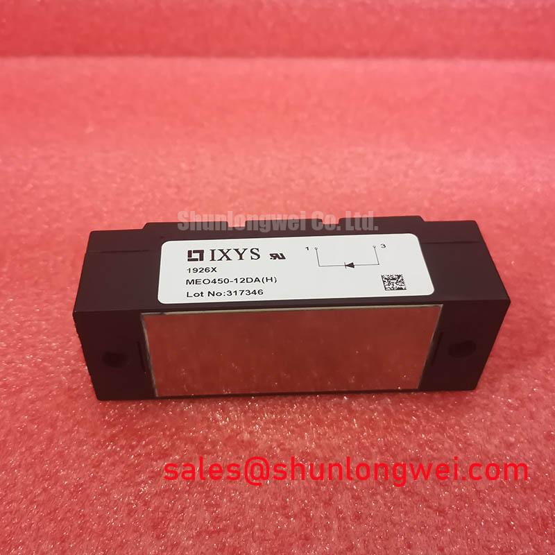
Inspect the mating heatsink and the module mounting face before applying interface material. Look for debris, raised marks, or uneven contact that could interrupt the thermal path, and confirm that the busbars reach their terminals without forcing the package out of position. Apply the interface material according to the equipment and material instructions, seat the module evenly, and inspect for signs of tilt after fastening. No mounting-torque or thermal-paste-thickness value is provided in the supplied specifications, so neither should be presented as an IXYS requirement for this model.
💡 Bench Tip: Keep the equipment isolated while making cold diode-mode comparisons, and use the documented terminal map rather than probing by assumed stud position.
The supplied package designation, SOT-227B / TO-240AA, is a starting point for a fit check, not a substitute for a dimensioned drawing. Compare mounting-hole positions, terminal locations, clearances, and the installed heatsink arrangement with the original documentation. If the unit is being fitted after a thermal fault, record the condition of the old interface and mating surface before cleaning them; that observation may help distinguish a contact problem from an electrical overload without claiming a single cause.
Thermal resistance from junction to case, Rth(j-c), cannot be verified from the supplied headline data because no value or measurement condition is provided. A Design Consideration is to evaluate the complete heat path under the intended load and ambient conditions, with the allowable junction temperature taken from the appropriate manufacturer documentation. The thermal-management discussion provides background on heat-path assessment, but it does not supply a module-specific mounting or temperature limit.
Layout can affect observed switching stress even when the diode itself is correctly mounted. Keep current paths and associated connections consistent with the approved equipment layout to limit parasitic effects, then check measured peak voltages against the relevant component ratings during system validation. Do not infer a permissible busbar inductance or an insulation margin from the 1200 V rating alone.
MEO450-12DA(H) Operational Boundaries: Harmonic Current and Line-Filter Assessment
For a soft-starter service check, begin at the equipment schematic: identify which devices control conduction and where, if anywhere, the MEO450-12DA(H) sits in the current path. A diode does not accept a firing-angle command, so a sweep of firing angles cannot be described as a control characteristic of this module. Harmonic current, power factor, and reactive-power behavior belong to the complete equipment and its load, not to the diode’s 1200 V and 453 A nameplate ratings.
If measured line current differs from a known-good installation, compare operating state, load, controlled-device commands, and line-filter connections before attributing the difference to this module. Check the diode paths with the equipment isolated, then use appropriately rated instruments to examine system waveforms under the equipment maker’s test procedure. A line filter should be assessed against the measured spectrum and the system’s applicable requirements; no filter limit or harmonic-compliance result is established by the supplied diode specifications.
Before releasing a repair, close the remaining documentation gaps: confirm the terminal diagram, the current-rating conditions, reverse-recovery data where switching behavior matters, thermal limits, mounting instructions, and fuse-coordination information from the applicable manufacturer documents. Record those checks alongside the cold-test readings so the next technician can distinguish what was measured on this unit from what was specified for the part.