

Content last revised on November 11, 2026
Benchtop Waveform Checks: Assessing Rectifier Stress on VUO50-08NO3
Isolate the incoming supply, discharge the DC link, and trace the rectifier terminals against the equipment schematic before connecting waveform probes to the VUO50-08NO3. Record cold forward and reverse meter readings with parallel circuit paths disconnected where practical. Compare corresponding conduction paths rather than assigning a universal acceptable voltage drop; connected capacitors, suppression components, and instrument test current can change the readings.
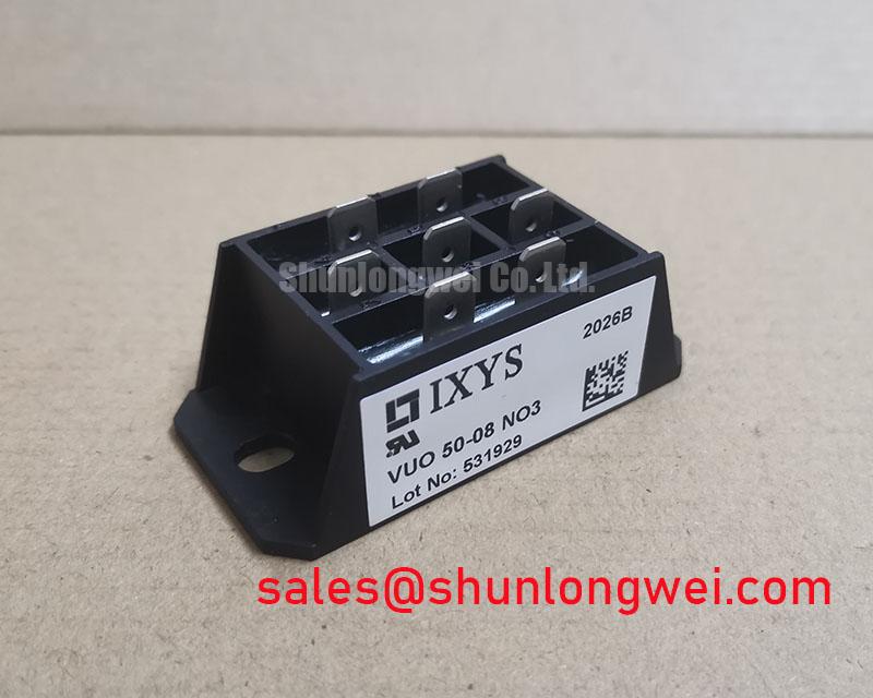
The specified product ratings are: Manufacturer: IXYS; Part Number: VUO50-08NO3; Repetitive Peak Reverse Voltage (VRRM): 800.0 V; Average Rectified Output Current: 50.0 A under the datasheet-specified conditions; Package: Module; Configuration / Topology: Three-Phase Diode Bridge. The product category is Bridge Rectifier Module. This is an uncontrolled rectifier, without gate terminals or an adjustable firing angle.
Design Consideration: Establish which component actually controls conduction before adjusting firing delay. A diode bridge conducts according to the instantaneous supply and load conditions; firing-angle adjustment applies to controlled semiconductor paths elsewhere in the documented circuit. Do not assign gate-drive requirements to this module from the category description. The VUO50-08NO3 product reference should remain tied to the exact purchasing designation and equipment bill of materials.
For a documented phase-controlled assembly, increasing firing delay generally reduces average rectified output under continuous-current conditions while changing displacement power factor and reactive demand. Discontinuous current and capacitor charging alter that relationship. Capture supply voltage, line current, and rectified output together when assessing controller adjustments; a DC reading alone cannot characterize harmonic current or commutation behavior.
Design Consideration: Treat suppression devices as part of the surrounding circuit. Evaluate MOV clamping behavior against the actual supply, surge exposure, protective coordination, and measured terminal stress. The 800.0 V reverse-voltage rating is not a MOV selection prescription. In equipment architecture reviews, VBO13-14AO2 is a separate rectifier-related component to assess against its own circuit role, not an assumed companion connection.
The Vienna rectifier three-phase active power factor correction topology provides useful context for distinguishing active input-current shaping from ordinary rectification; it does not establish that this module implements active power factor correction.
Field Diagnostics & Commissioning: External Thyristor Firing in Assemblies Using VUO50-08NO3
Locate the gate and cathode connections on the equipment schematic before interpreting any firing pulse near the rectifier assembly. Where an external thyristor stage is present, measure the pulse at that device’s referenced terminals rather than at the controller output alone. Wiring impedance and return-path disturbance can make those waveforms differ.
Design Consideration: Assess trigger-current amplitude, pulse duration, repetition, and rise time against the controlled device’s gate specifications. Trigger current and voltage, latching current, and holding current describe different operating conditions. A sustained gate pulse cannot ensure conduction after anode current falls below the relevant holding condition. Pulse-train changes therefore require simultaneous observation of gate drive and main-circuit current, not an assumed universal strong-trigger setting.
The following comparison separates the supplied VUO50-08NO3 ratings from checks needed before evaluating another part. “Consult datasheet” identifies a verification task, not an equivalence claim.
| Selection item | VUO50-08NO3 | VVZF70-08IO7 |
|---|---|---|
| Manufacturer | IXYS | Consult datasheet |
| Repetitive Peak Reverse Voltage (VRRM) | 800.0 V | Consult datasheet |
| Average Rectified Output Current | 50.0 A under the datasheet-specified conditions | Consult datasheet |
| Package | Module | Consult datasheet |
| Configuration / Topology | Three-Phase Diode Bridge | Consult circuit diagram |
| Terminals, mounting torque, surge I²t, thermal resistance | Consult datasheet | Consult datasheet |
A comparison with VVZF70-08IO7 should begin with internal connections and terminal functions before considering electrical ratings. For potential use within a grid-tied static var compensator or thyristor-switched capacitor cabinet, establish the particular rectifier subsystem and its voltage exposure; the equipment name does not establish compatibility with the main power circuit.
Preventing Spurious Faults: Junction-to-Heatsink Heat Dissipation Guidelines for VUO50-08NO3
Inspect the heatsink contact surface for contamination, damaged threads, and uneven seating before refitting the module. Remove deteriorated interface material using a process compatible with the assembly, then apply the specified replacement material without introducing debris or mechanical distortion. Neither baseplate composition nor a numerical junction-to-case thermal resistance follows from the package description.
Engineering Recommendation: Use the applicable mounting instructions and calibrated tooling for both mounting fasteners and power terminals. Distinguish terminal torque from heatsink attachment torque. Assess thermal performance under representative load and ambient conditions, recording measurement location and operating state so later inspections remain comparable.
Maintenance Note: Periodically monitor terminal temperature rise and clear obstructed cooling passages before increasing the operating load.
Design Consideration: Set inspection intervals from contamination exposure, thermal cycling, and observed interface condition rather than an invented service-life figure. In humid environments, examine enclosure moisture control and condensation evidence before energization. For fuse coordination, compare protective-device clearing characteristics with the semiconductor’s documented surge withstand under matching conditions; average current alone is insufficient.
The related Mastering GaN Power Transistor Design article offers broader switching-layout context, not VUO50-08NO3 specifications. During recurring fault investigations, separate terminal heating, restricted airflow, and electrical transients through repeatable measurements before changing protection or control settings.