

Content last revised on November 10, 2026
MCD501-16IO2 Thermal-Electrical Optimization: IEC 61000-4-5 Industrial Surge Immunity and Practical Tuning
With the input supply isolated and stored energy discharged, trace the rectifier power terminals and gate connections before disconnecting the MCD501-16IO2. Record the installed conductor arrangement and compare it with the replacement circuit diagram; matching the housing alone does not establish electrical compatibility. Check terminal contact surfaces for heat discoloration and inspect the mounting interface for uneven contact before reconnecting the assembly.
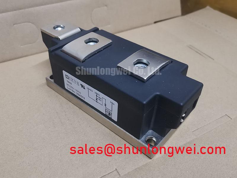
The primary specifications are Manufacturer: IXYS; Part Number: MCD501-16IO2; Repetitive Peak Reverse Voltage (VRRM): 1600.0 V; Average On-State Current (IT(AV)): 501.0 A under the datasheet rating conditions; Package: TO-240AA; and Configuration / Topology: Thyristor / Diode Module. Connection planning must follow the thyristor/diode topology rather than assume two controllable thyristors. For current-rating conditions, installation-specific thermal resistance, surge withstand, gate limits, terminal identification, and tightening torque: consult the manufacturer datasheet.
Map the incoming protection path from the supply terminals through the protective devices to the module before selecting a MOV or changing an RC snubber. Design Consideration: surge coordination should account for the supply configuration, prospective surge current, protective-device residual voltage, and wiring inductance. The relevant surge-immunity reference is IEC 61000-4-5, not “IEEE 61000-4-5”; equipment-level testing does not establish independent module compliance.
The 1600.0 V repetitive reverse rating is an electrical boundary, not a MOV clamping target. Evaluate the voltage actually appearing across the semiconductor during the applicable surge test, including the contribution from interconnecting conductors. An RC network should address the measured transient response without introducing excessive repetitive discharge current or resistor heating. Its component values remain a system design decision supported by waveform and temperature measurements.
For fuse coordination, compare the proposed fuse’s total clearing I²t against the semiconductor withstand information at compatible pulse duration, initial temperature, and voltage conditions. The coordination record should identify the fuse, prospective fault current, clearing behavior, and module withstand basis. Average current alone is not a sufficient selection criterion. Check that the protective path also covers the diode branch rather than considering only the controlled device.
For potential integration into a medium-frequency induction melting or hardening furnace, engineers should evaluate this module’s rectifier-stage role separately from the downstream frequency-conversion stage. The MCD162-14IO1 provides a related module reference when documenting surrounding rectifier arrangements, not an assumed companion or interchangeable part. The Powering the Digital Backbone article offers broader switching-stage context; its IGBT discussion does not replace thyristor-specific protection requirements.
Assembly Integrity and Layout Architecture: Thermal Interface Material Spreading for MCD501-16IO2
Inspect heatsink flatness, remove old interface residue, and check that busbar alignment does not pull the module away from its mounting plane. Design Consideration: thermal interface material should fill surface irregularities while preserving consistent mechanical contact. Apply the selected material according to its installation instructions and use the module’s specified fastening sequence and torque, distinguishing mounting fasteners from electrical terminal fasteners.
Evaluate the junction-to-case thermal path using the manufacturer’s thermal resistance data and the losses associated with the actual current waveform. Phase-controlled conduction produces a different thermal duty from an assumed continuous current. For pulsed loading, use the applicable transient thermal impedance, Zth, with pulse duration and repetition history to assess peak junction temperature rather than relying solely on an averaged heatsink reading.
Inspect clearance around main terminals and creepage paths across insulating surfaces after fitting the conductors. Cable lugs, displaced washers, contamination, and enclosure hardware can alter the completed assembly’s insulation geometry. Assess the equipment’s required distances using its applicable insulation-coordination rules and environmental conditions; the TO-240AA designation does not certify the finished installation.
Practical tip: Support and align the busbars before tightening the terminals so that conductor preload does not distort the mounted module. During replacement assessment, compare the MCC162-08IO1 only through a documented review of circuit configuration, ratings, terminal mapping, and mechanical interfaces; membership in the same manufacturer’s range does not establish interchangeability.
MCD501-16IO2 Thermal-Electrical Optimization: Preventing Localized Turn-On Heating During Firing
Measure the firing pulse at the module’s gate and cathode connections rather than only at the controller output. Design Consideration: gate-loop inductance and connection resistance can reshape the delivered pulse, affecting initial conduction spreading. Compare measured gate current and voltage with the manufacturer’s IGT, VGT, pulse-power, and permitted gate-drive conditions; no universal gate-current rise-rate threshold should be imposed on this model without that specification.
A sustained pulse or pulse train can support triggering when load current develops slowly, but the gate drive must remain within its permitted duty. Distinguish gate-pulse duration from anode latching and holding behavior: extending a pulse does not guarantee sustained conduction when the main current is insufficient. Investigate intermittent firing against the commanded phase angle, actual load current, and gate waveform before assigning a cause.
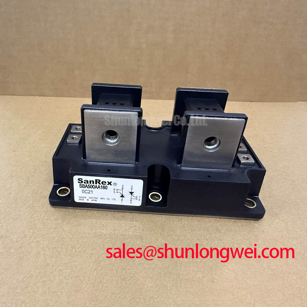
Keep the gate-return path close to its associated gate conductor and separate it from high-current power routing where practical. Capacitive transient coupling deserves attention, but IGBT Miller-plateau drive prescriptions should not be transferred to this thyristor/diode module. General device context is available from SanRex Sansha Electric Power Semiconductor Modules; IXYS device limits remain the basis for acceptance.
Finally, compare firing symmetry across the rectifier branches under representative loading. Phase-angle imbalance can affect current sharing, input harmonics, and heating. Evaluate any firing-control or line-reactor changes at equipment level, then verify terminal temperatures and conduction waveforms through the intended operating range.