
Content last revised on September 19, 2026
Transient Dynamics & Electrical Design: AC-to-DC Transfer Characteristics of MEO450-12DA(K)
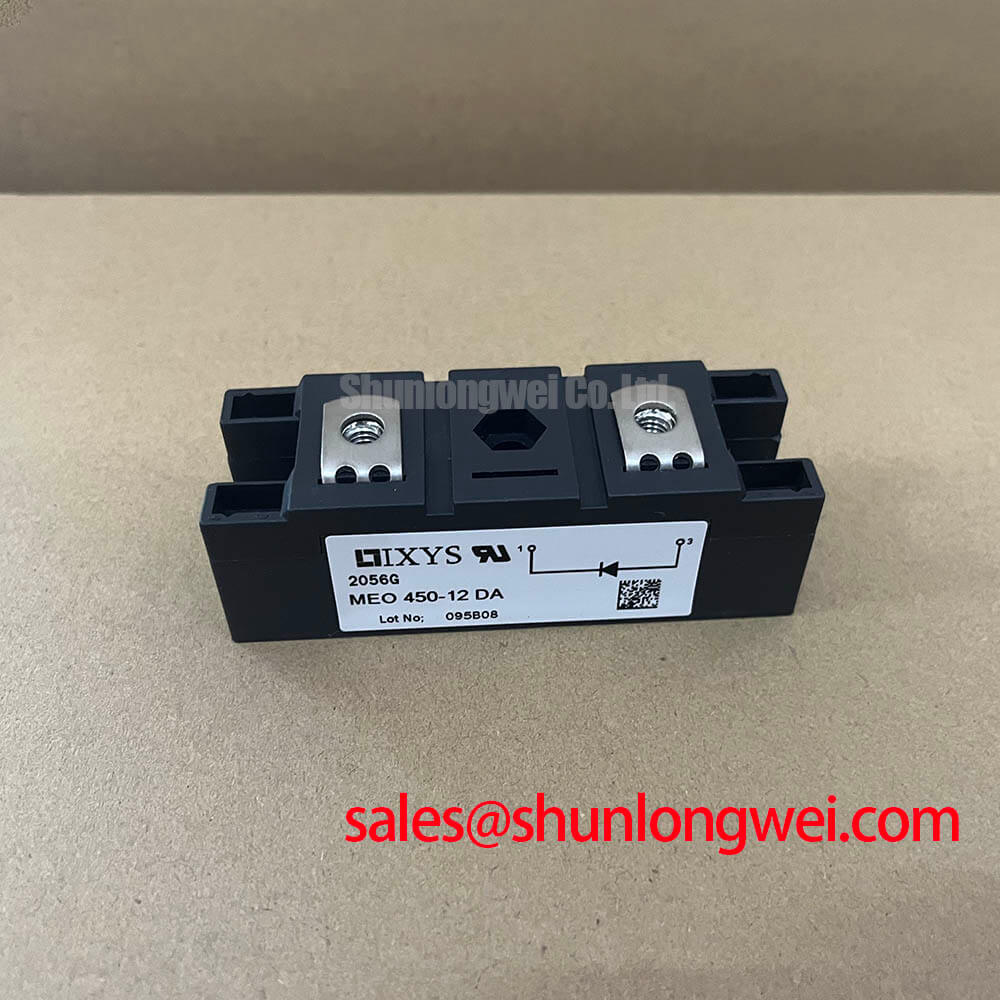
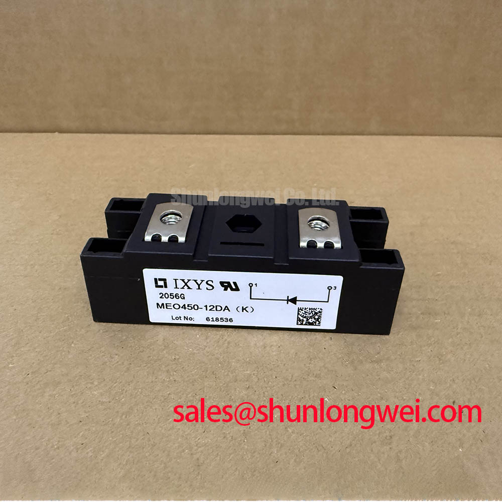
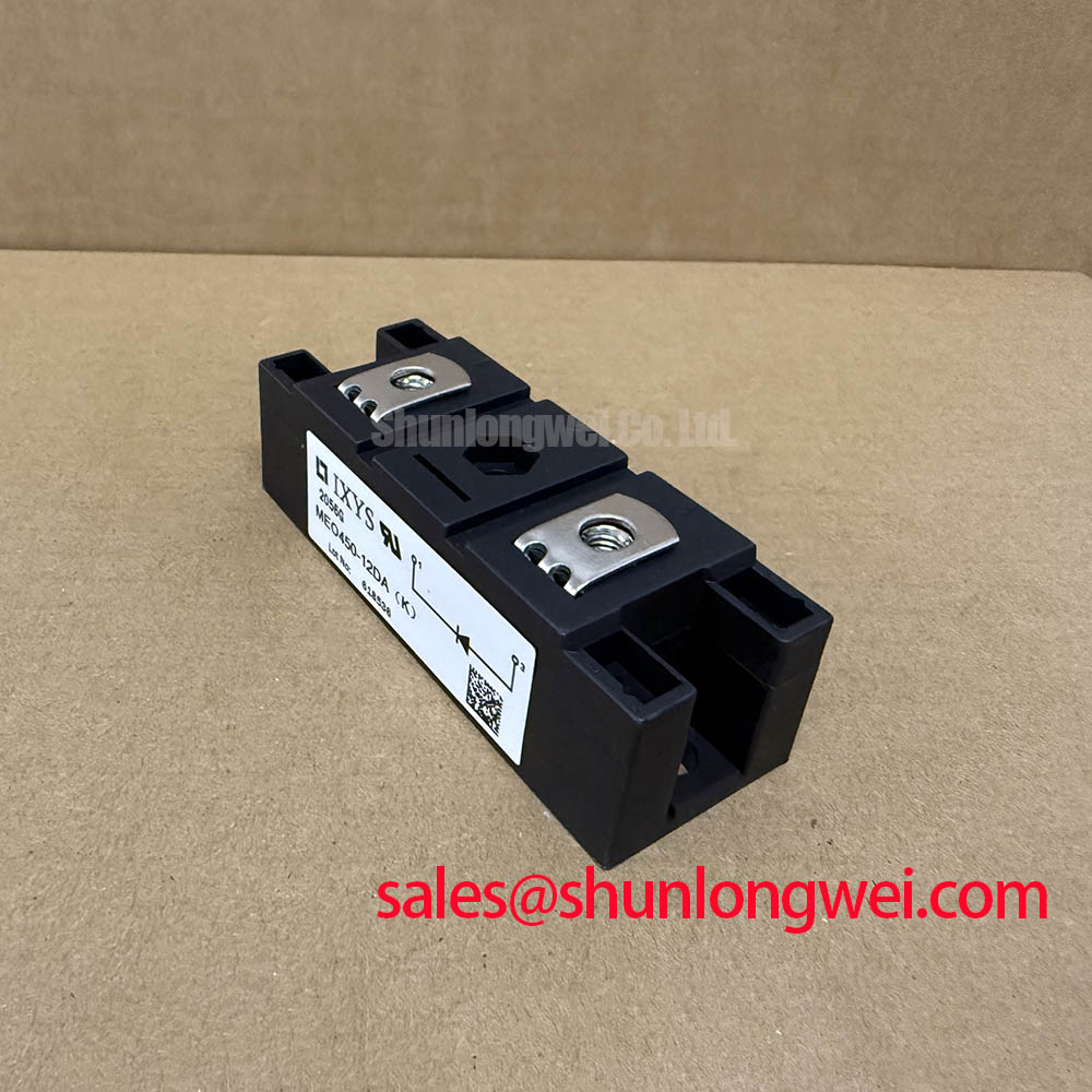
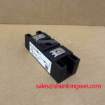
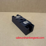
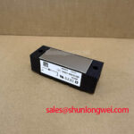
With the assembly isolated from all stored energy, begin incoming inspection by confirming that the power terminals correspond to the original equipment connection drawing, then use a multimeter diode function to compare the forward conduction paths of the two internal diode sections. The MEO450-12DA(K) is an IXYS dual diode module, so a cold-state diode check should show directional conduction consistent with the external terminal arrangement; it does not provide gate terminals, gate-trigger characteristics, or controllable firing-angle operation.
The official electrical boundary is 1200 V VRRM at junction temperatures from −40 °C to 150 °C. Its official average forward-current rating is 486 A IFAV, specified at TC = 85 °C with 180° rectification. The 760 A IFRMS rating describes the RMS current capability stated for the module. These values must be evaluated against the original cooling arrangement, line waveform, current sharing arrangement, and enclosure thermal conditions rather than treated as universal system output ratings.
In a high-voltage three-phase motor solid-state soft starter, phase-angle control is normally performed by external thyristor assemblies or other controllable semiconductor stages. At firing angles between 0° and 150°, the controlled stage changes the portion of each AC cycle delivered to the motor, affecting displacement power factor, harmonic current, and reactive power demand. A dual diode module can instead appear in an associated rectifier, clamp, freewheel, or auxiliary DC conversion path, depending on the original power schematic. Its role must be confirmed from that schematic before replacement or redesign work begins.
For AC-to-DC transfer analysis, trace the current path through each line condition and identify whether the module conducts continuously, commutates between diode branches, or carries transient charging current. The 0.85 V VT0 threshold-voltage figure and 0.45 mΩ rT forward slope resistance are official values provided for power-loss calculation only. They are useful when comparing expected conduction loss at the intended operating current, but they are not fixed forward-voltage measurements for bench acceptance testing.
| Official Specification | Condition | Value |
|---|---|---|
| Repetitive peak reverse voltage | TVJ = −40 °C to 150 °C | 1200 V |
| Average forward current | TC = 85 °C, 180° rectified | 486 A |
| RMS forward current | Specified by manufacturer | 760 A |
| Threshold voltage | For power-loss calculation only | 0.85 V |
| Forward slope resistance | For power-loss calculation only | 0.45 mΩ |
Where a repair design also contains a controlled semiconductor bridge, the 2DI150M-120 can be reviewed as a separate same-voltage-class reference item. Terminal count, current path, mounting geometry, thermal interface, and circuit function still require independent verification; a nominal voltage class alone does not establish interchangeability.
💡 Bench Tip: Record the cold diode-mode readings for both conduction directions before mounting, then compare them with a known-good module measured using the same meter and lead orientation.
Transient Dynamics & Electrical Design: Baseplate Thermal Resistance on MEO450-12DA(K)
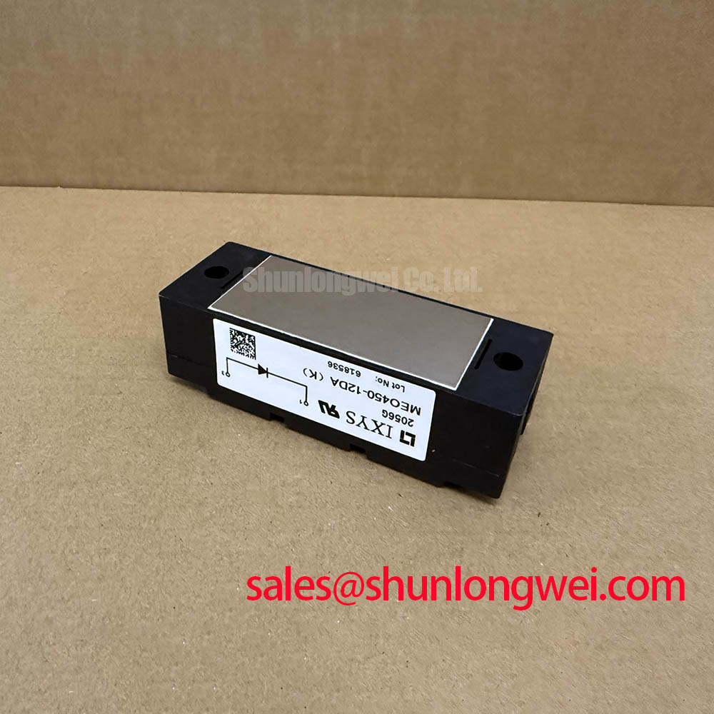
The official junction-to-case thermal resistance is 0.08 K/W per diode. This figure applies from each diode junction to the module case under the manufacturer’s stated thermal model; it does not include thermal interface material, heatsink spreading resistance, airflow, coolant performance, cabinet temperature, or the thermal behavior of neighboring power devices. For service evaluation, inspect the contact face for contamination, uneven compound transfer, corrosion, or mechanical damage before interpreting any overtemperature event.
Apply thermal compound as a controlled thin and uniform interface layer according to the equipment builder’s mounting procedure. A patchy imprint after removal can indicate that flatness, clamping sequence, mounting hardware, or heatsink surface condition should be checked. Avoid assuming that a low case temperature proves low junction temperature, because the actual heat path depends on current waveform and the complete heatsink system.
⚠️ Field Alert: If the equipment uses M5 mounting hardware, the general industry mounting range of 2.5–3.5 N·m is a design consideration only and must not override the original equipment or module-package mounting instruction.
The module has a specified junction-temperature range of −40 °C to 150 °C. During commissioning, engineers should correlate heatsink temperature, conduction interval, and line current with the original control sequence. A rising thermal trend may result from restricted cooling, altered firing behavior in an external controlled stage, unequal parallel-path loading, deteriorated interface contact, or line disturbances. Measurement across the complete assembly is more informative than assigning a single cause from temperature alone.
The isolation test rating is 3000 V~, applied at 50/60 Hz RMS for 1 minute, as an official specification. This test voltage is a defined production-style dielectric test condition, not a blanket statement of system insulation coordination, installation category, long-term insulation endurance, or surge withstand. The installer should maintain creepage, clearance, protective-earth, enclosure, and test procedures required by the finished equipment design.
For a larger discussion of where power-semiconductor thermal verification sits within industrial conversion equipment, see Industrial Applications. That technical context supports system-level assessment but does not change the published ratings of this diode module.
MEO450-12DA(K) Circuit Protection & Reliability: Calibrating AC Line Surge Immunity, Lightning Transients
Protection work should start with a line-to-line and line-to-earth review of the actual soft-starter input topology. The 1200 V VRRM rating defines the repetitive reverse-voltage limit of the MEO450-12DA(K), while real switching and line transients depend on cable inductance, transformer behavior, contactor operation, external thyristor commutation, snubber placement, and the protection network already present in the cabinet.
Metal-oxide varistors and RC snubbers are system components, not published internal features of this module. As a Design Consideration, their clamping behavior and energy duty should be selected against the measured line environment and verified under the equipment’s intended operating states. Engineers should assess surge behavior according to the applicable finished-equipment standard, commonly IEC 61000-4-5 where relevant, instead of assigning independent EMC compliance to the diode module itself.
The official non-repetitive peak forward surge-current rating is 15000 A ITSM for a 10 ms, 50 Hz sine-wave event at TVJ = 150 °C. The stated fusing value is 1125 × 10³ A²s under the same junction-temperature and 10 ms condition. These factory values provide the starting point for fault-path and fuse-coordination review, but they do not by themselves select a fuse. Fuse clearing characteristics, prospective short-circuit current, source impedance, conductor limits, coordination with other protective devices, and the original equipment safety design remain system-determined.
| Fault and Isolation Parameter | Official Condition | Official Value |
|---|---|---|
| Surge forward current | TVJ = 150 °C, 10 ms, sine 50 Hz | 15000 A |
| I²t value for fusing | TVJ = 150 °C, 10 ms | 1125 × 10³ A²s |
| Isolation test voltage | 50/60 Hz RMS, 1 minute | 3000 V~ |
A diode module has no transistor safe-operating-area graph and no gate drive loop. Still, the measurement discipline described in the ROHM transistor safe operating area application is useful as a general reminder: capture the relevant voltage and current conditions at the device terminals, then compare them with the applicable published limits rather than relying on assumptions from cabinet-level symptoms.
Where an auxiliary rectification section is present upstream or alongside the main power path, the 2DI75M-120 is a related module that can be examined for its own circuit role. Any comparison should include its individual datasheet ratings and the original circuit connection, not only the shared 1200 V class.
Benchtop Waveform Tuning: Mitigating Stress via Three-Phase Back-to-Back Thyristor Voltage on MEO450-12DA(K)
For a three-phase soft starter, back-to-back thyristors in each phase can control motor terminal voltage during acceleration. The MEO450-12DA(K) is not a back-to-back thyristor module and cannot receive phase-angle trigger pulses. Its contribution, if used in the equipment, must be understood as a diode conduction or rectification function established by the actual wiring diagram.
Motor locked-rotor current can be several times the motor rated current, and controlled ramping is used to reduce electrical and mechanical stress during starting. The final current limit, ramp profile, bypass sequence, and protection thresholds are determined by the motor data, driven load, supply capacity, thyristor ratings, cooling system, and the starter controller. Designers should verify these settings with measured phase current and voltage waveforms, particularly during starts at different load conditions.
When reviewing an associated diode path, check whether the observed waveform agrees with expected rectification intervals and whether reverse voltage remains inside the module’s 1200 V repetitive limit. Verify terminal torque and busbar contact using the original equipment documentation. Loose or uneven terminal interfaces can introduce localized heating and unstable voltage measurement results, while excessive mechanical force can damage connection hardware or distort the mounting interface.
Control-network timing also matters in a soft starter. A deterministic industrial communication system can influence when commands, permissives, and bypass transitions occur, although it does not alter the electrical rating of the diode module. For context on deterministic communication behavior, consult the Ethernet Powerlink deterministic real-time industrial network standard. During bench validation, compare controller command timing, phase voltage, motor current, and any auxiliary DC rail associated with the diode module against a known-good sequence.
If waveform distortion, asymmetric phase current, or unexpected heating is observed, isolate the evidence before replacing parts. Confirm line balance, thyristor trigger synchronization, snubber condition, busbar continuity, cooling contact, and diode polarity. This approach keeps the evaluation tied to measurable circuit behavior and to the official 486 A, 760 A, 1200 V, and thermal specifications of the IXYS MEO450-12DA(K).