


Content last revised on January 13, 2026
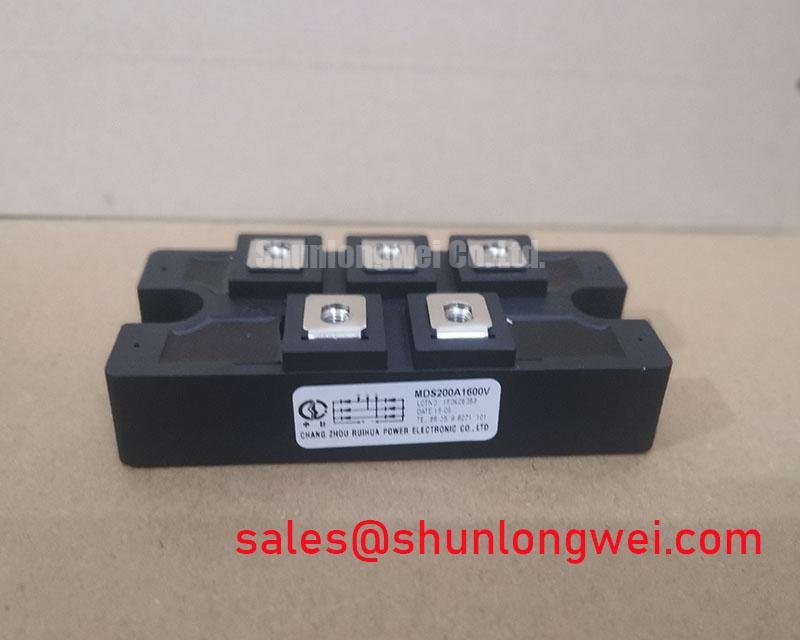
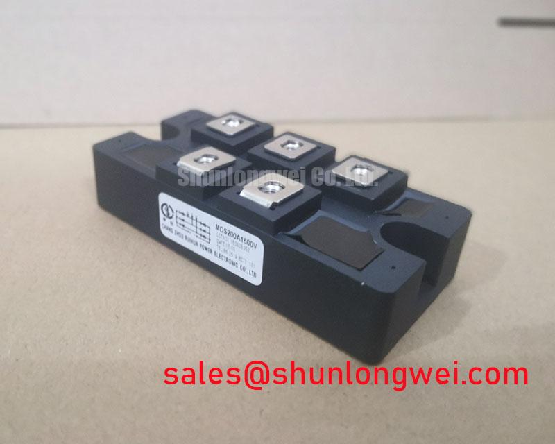
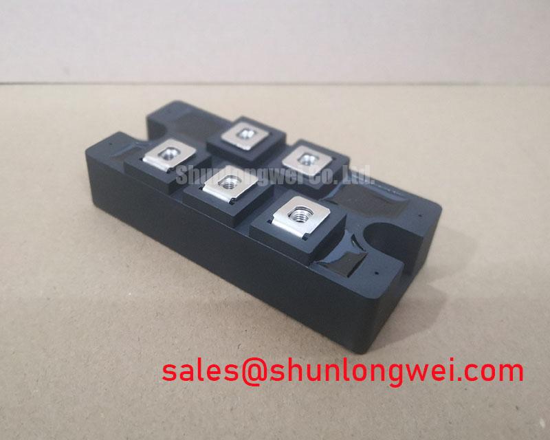
MDS200A1600V | Integrated 3-Phase Rectifier & Brake Chopper PIM
The MDS200A1600V is an expertly engineered Power Integrated Module (PIM) designed to streamline the front-end and braking circuits of high-power systems. By co-packaging a three-phase rectifier bridge and a robust IGBT brake chopper, this module provides a compact, reliable, and thermally efficient solution, significantly reducing design complexity and assembly time for power conversion applications up to the 75 kW class.
Product Highlights Overview
This module is engineered not just as a component, but as a system-level solution. It addresses the core challenges of power density, reliability, and manufacturing efficiency. Key engineering advantages include:
- System Integration: Combines a 1600V three-phase diode bridge and a 200A/1200V IGBT chopper in a single, electrically isolated package. This integration minimizes stray inductance and simplifies PCB layout and heatsink mounting.
- Robust Power Handling: Rated for 200A, it is perfectly suited for demanding applications like Variable Frequency Drives (VFDs) and servo systems where managing regenerative energy is critical.
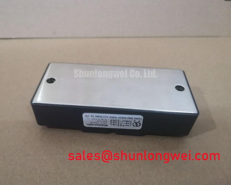
- Optimized Thermal Performance: Built on an industry-standard package with an isolated copper baseplate, ensuring efficient heat transfer to the heatsink and improving overall system reliability and lifetime.
- Simplified Bill of Materials (BOM): Replaces multiple discrete components, reducing sourcing complexity, inventory management, and assembly costs.
Key Parameters Overview
The following specifications are critical for design engineers. They highlight the module's capacity and electrical characteristics. For comprehensive data, including thermal curves and dynamic characteristics, download the complete MDS200A1600V datasheet.
| Parameter | Description | Value |
|---|---|---|
| VRRM | Diode Maximum Repetitive Reverse Voltage | 1600 V |
| VCES | IGBT Collector-Emitter Voltage | 1200 V |
| IF(AV) | Rectifier Diode Average Forward Current | 200 A |
| IC | IGBT Continuous Collector Current (@ TC=80°C) | 200 A |
| VCE(sat) | IGBT Collector-Emitter Saturation Voltage (@ IC=200A) | 2.5 V (typ) |
| VF | Diode Forward Voltage (@ IF=200A) | 1.3 V (typ) |
| Tj(max) | Maximum Operating Junction Temperature | 150 °C |
Application Scenarios & Value Proposition
The MDS200A1600V excels in applications where AC power is rectified to a DC bus and where regenerative energy needs to be managed. Its integrated nature provides distinct advantages in each scenario:
- Motor Drives (VFDs): In a typical VFD, the module's rectifier section converts the incoming three-phase AC to a stable DC bus. During motor deceleration, the inverter returns energy to the DC bus, causing its voltage to rise. The module's IGBT chopper activates, shunting this excess energy through an external braking resistor. This prevents overvoltage faults and allows for rapid, controlled braking—a critical function in cranes, elevators, and conveyors.
- Servo Drives: Precision robotics and CNC machines require fast acceleration and deceleration cycles. The MDS200A1600V provides the robust front-end rectification and the high-speed braking capability needed to absorb regenerative pulses, ensuring tight position control and protecting the drive. For more details on this topic, see our guide on the role of IGBTs in robotic servo drives.
- High-Power UPS & Power Supplies: In certain UPS topologies, the module can serve as the primary AC-DC conversion stage. The integrated chopper can also be used for applications like high-power boost Power Factor Correction (PFC) stages, contributing to a more efficient and compact power supply design.
Technical Deep Dive: The PIM Advantage
The move from discrete components to a PIM (Power Integrated Module) like the MDS200A1600V represents a strategic design choice. Integrating the rectifier and chopper significantly reduces the parasitic inductance in the power circuit loop between the DC bus capacitors and the switching elements. This reduction minimizes voltage overshoot during IGBT turn-off, which in turn reduces the need for oversized snubber circuits and enhances the overall reliability of the system. This simplification of the power stage is a core benefit when considering the total cost of ownership, from design to manufacturing and long-term service. For a deeper understanding of the components involved, explore our complete analysis of IGBT modules.
Frequently Asked Questions (FAQ)
Why is the module labeled 1600V if the IGBT is only rated for 1200V?
This is an excellent and common engineering question. The 1600V rating refers to the VRRM of the input rectifier diodes. This high blocking voltage provides a significant safety margin for operation on 380V, 480V, and even up to 600V AC lines, where peak voltages and transients can be substantial. The IGBT, which operates on the rectified DC bus, is rated for 1200V. For a 480V AC line, the nominal DC bus voltage is approximately 678V (480 * √2), making a 1200V IGBT the industry-standard choice, providing ample headroom against switching-induced voltage spikes.
What is the most critical design consideration when using the brake chopper?
The most critical aspect is the physical layout of the braking circuit. The high-current loop—from the DC bus capacitor, through the IGBT, to the external braking resistor, and back to the capacitor—must be as short and wide as possible. Excessive inductance in this path can cause severe voltage overshoot across the IGBT when it turns off, potentially leading to device failure. Proper layout is just as important as a well-designed gate drive circuit. For more tips on this, read our guide to robust IGBT gate drive design.