

Content last revised on October 7, 2026
High-Frequency Commutation Loop Inductance Minimization in High-Power Arrays
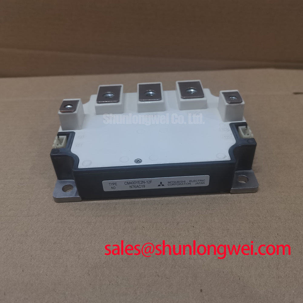
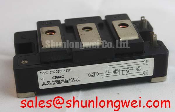
Isolate the heavy-duty variable frequency AC motor drive, discharge its DC link, and compare the installed module’s terminal connections with the drive schematic before removing a suspected failed device. The CM200DU-12H is a Mitsubishi Electric IGBT module with a rated voltage of 600 V and rated current of 200 A, both Official Specifications. Those ratings identify the part; they do not establish that another drive’s gate circuit, mounting arrangement, or switching conditions are compatible.
With the module disconnected from the surrounding circuit, a cold multimeter check can screen for a pronounced short across the main power terminals. Compare results with the circuit diagram and the known-good path where available. A reading taken in place can include the DC-link capacitors, snubber, motor wiring, or parallel devices, so it should not be treated as a verdict on the module alone. Record terminal discoloration, loose connections, and damage around the mounting surface before cleaning or disassembly removes useful evidence.
During switching, stray inductance in the DC-link and commutation path adds voltage overshoot to the DC-link voltage. As a Design Consideration, keep the outgoing and return current paths close together and avoid unnecessary loop area. Symmetrical busbar geometry matters especially when a drive uses multiple power positions: unequal paths can produce unequal switching stress even where the installed modules carry the same nameplate rating. The permissible layout and any snubber capacitor value must be determined from the actual bus voltage, switching waveform, insulation clearances, and measured peak voltage, rather than from the module’s current rating alone.
If a drive trips during rapid current changes, inspect the DC-link connections and snubber path as well as the module. An oscilloscope measurement made with appropriately rated probes can distinguish a switching overshoot from a steady DC-link rise. Check the observed peak against the 600 V Official Specification under the drive’s relevant operating conditions. Probe placement and measurement-loop length matter: a poor measurement connection can add ringing that is not present at the module terminals.
For an in-place replacement assessment, compare the original terminal arrangement, gate-drive requirements, mounting dimensions, and circuit function—not just voltage and current markings. The CM200DY-24E is a separate model to evaluate against those requirements, not an assumed drop-in substitute for the CM200DU-12H.
Thermal Interface Material (TIM) Thickness Uniformity and Void Minimization
Clean the heatsink and module contact surfaces, then inspect them under good light before applying fresh thermal interface material. Raised burrs, embedded debris, and uneven residue can hold part of the module away from the heatsink. The practical objective is continuous contact with a thin, uniform interface; a thicker layer is not a substitute for correcting a damaged or unsuitable mounting surface. The required material, application method, and fastening procedure should follow the applicable module documentation and drive assembly instructions.
⚠️ Field Alert: Do not reuse a disturbed thermal interface without inspecting and preparing both mating surfaces before remounting the module.
Bring mounting screws down progressively in the sequence specified for the assembly so that the module seats evenly. A single fully tightened screw can distort contact while other fasteners remain loose. If mounting torque or permitted surface flatness is unavailable for this exact assembly, obtain the appropriate documentation rather than adopting a generic value as an Official Specification. After installation, compare temperature measurements at repeatable locations under a controlled operating condition; an unexplained difference warrants inspection of contact pressure, cooling flow, and electrical loading.
Temperature evidence must also be read alongside switching evidence. Freewheeling-diode reverse recovery can contribute to current transients during commutation, while the surrounding loop inductance affects the resulting voltage response. Snubber design and busbar layout may reduce unwanted ringing, but neither provides a stand-alone guarantee of electromagnetic compatibility. If noise appears after service, compare waveforms and connections with the drive’s documented arrangement before changing components. The Field Engineer’s Handbook offers broader testing and failure-analysis context; the installed drive remains the reference for its own thermal and switching limits.
Thermal Feedback & V_CE(sat) Positive Temperature Coefficient Equalization
When a drive has parallel power paths, verify their physical connections before attributing unequal current to the semiconductor devices. Compare busbar joints, gate wiring, heatsink contact, and temperature-sensor placement. A loose power joint or asymmetric gate loop can change the observed behavior without changing the module’s identity. Document the original routing before disconnecting leads, particularly where several similar-looking gate and power connections are close together.
A positive temperature coefficient of collector-emitter saturation voltage can aid static current sharing under operating conditions where that behavior applies. It should not be assumed to characterize the CM200DU-12H across all currents and temperatures without the relevant device curves. As a Design Consideration, assess static sharing at stabilized temperature separately from dynamic sharing during switching. The latter depends strongly on gate-drive timing, wiring impedance, and commutation-path symmetry; thermal feedback alone cannot correct a mismatched switching path.
For a practical check, capture comparable gate and power waveforms at equivalent positions using the same probe arrangement and operating state. Look for differences in turn-on or turn-off timing, ringing, and temperature trend rather than assigning a fault from one isolated reading. Keep gate-return routing consistent with the documented drive layout, and verify measured switching peaks against the module’s rated voltage. If the drive’s original test procedure defines acceptance criteria, use those criteria instead of a generic current-sharing percentage.
Dynamic Braking Chopper Operation & Regenerative Deceleration Energy Absorption
When an AC motor decelerates, energy returned through the inverter can raise the DC-link voltage. If the drive uses a braking chopper and resistor, trace that circuit on the equipment schematic before assigning a braking function to the CM200DU-12H. The supplied module ratings do not establish that a braking IGBT is built into this module, nor do they specify a suitable external resistor. Those are properties of the complete drive arrangement.
On a drive that faults during deceleration, first compare the DC-link voltage trend with the drive’s recorded fault and command state. Then inspect the documented chopper path, resistor connections, and associated protection circuit with power safely removed. An open resistor path, a connection problem, and an unsuitable deceleration setting can produce different evidence; the fault indication alone does not identify the failed part. Resistor energy capacity, chopper switching duty, and DC-link limits must be established from the drive and motor operating profile by the system engineer.
Control strategy can change how abruptly the inverter demands torque and current. Direct torque control describes one approach to motor torque control, while the Clarke transformation describes a coordinate conversion used in motor-control analysis. Neither determines the braking hardware installed in a particular drive. Use the drive schematic, measured DC-link behavior, and braking settings to separate a deceleration-energy problem from a module switching fault.