Content last revised on September 26, 2026
QM200HH-H Circuit Protection and Reliability in Harsh Industrial Drives
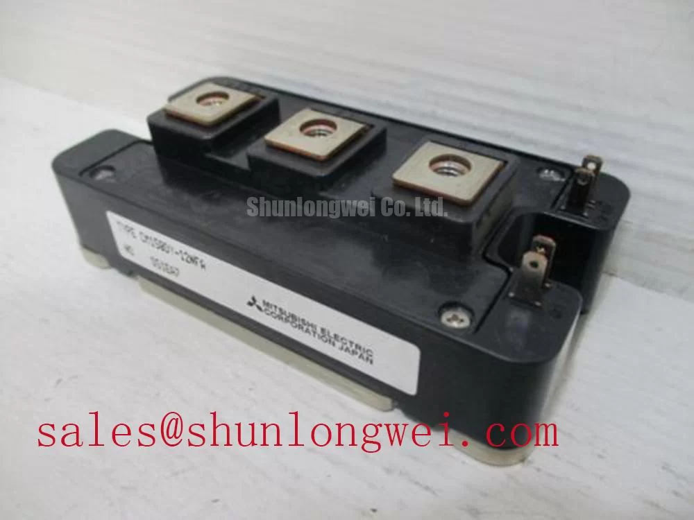
The Mitsubishi Electric QM200HH-H is a high current power transistor and Darlington module intended for evaluation in demanding industrial power conversion equipment, including heavy duty variable frequency AC motor drives. Its documented ratings provide the starting point for electrical and thermal compatibility checks, while switching behavior, protection performance, and installation quality remain system level responsibilities.
| Parameter | Symbol | Official Specification |
|---|---|---|
| Collector emitter voltage | VCEX | 600 V, VEB = 2 V |
| Continuous collector current | IC | 200 A at TC = 25°C |
| Collector dissipation | PC | 1040 W |
| Operating junction temperature | Tj | −40°C to +150°C |
| Collector emitter saturation voltage | VCE(sat) | 2.0 V maximum at IC = 200 A, IB = 2.6 A |
| Base emitter saturation voltage | VBE(sat) | 2.5 V maximum at IC = 200 A, IB = 2.6 A |
| DC current gain | hFE | 75 minimum at IC = 200 A, VCE = 2 V or 5 V |
| Junction to case thermal resistance | Rth(j-c) | 0.12°C/W, transistor part |
| Dielectric insulation voltage | Visol | 2500 V AC for 1 minute at 60 Hz |
Start protection validation at the complete commutation loop rather than at the module alone. The QM200HH-H has a documented 600 V VCEX rating under the stated condition, but the voltage appearing across the device during motor drive switching also depends on DC bus voltage, wiring inductance, diode recovery, motor cable behavior, and the switching sequence. A short oscilloscope measurement across the collector emitter terminals during turn off is therefore more useful than relying on the nominal bus label.
The published insulation specification is 2500 V AC for one minute at 60 Hz. This value should not be converted into an assumed reinforced barrier rating above 5 kV, nor should it be treated as a common mode transient immunity rating. CMTI belongs to the selected driver, optocoupler, or digital isolator and must be confirmed from that component’s documentation. Designers should verify isolation clearance, creepage, pollution conditions, cable routing, and transient behavior as one coordinated safety assessment.
When a drive shows intermittent base drive pulses or unexplained overcurrent trips, isolate the module from the base control circuit and compare the command waveform with the return path at the power device. A misplaced reference connection, excessive common impedance, or capacitive coupling across the isolation barrier may produce a misleading trigger waveform. Check the driver supply, return conductor, protective clamp path, and probe connection before assigning the fault to the QM200HH-H.
The module’s specified VBE(sat) is 2.5 V maximum at the stated current and base current conditions. This figure is not a universal drive voltage prescription. The replacement circuit should reproduce the original bias and protection conditions, with base current, turn off control, and transient clamping verified on the actual assembly. If the equipment contains an associated HMI, visual inspection methods may be referenced through Automated Optical Inspection concepts for board assembly review, while electrical acceptance still requires live circuit measurements.
Preventing Spurious Faults Through Heatsink Contact and Switching Layout
Thermal installation should be checked before high current testing. The official 1040 W collector dissipation rating does not describe the complete heatsink assembly, thermal interface condition, enclosure airflow, or transient junction temperature. Clean both mating surfaces, inspect the baseplate and heatsink for distortion, and apply the thermal interface material according to the material supplier and equipment manufacturer instructions. Excess interface compound, trapped air, uneven pressure, or a contaminated surface can increase the junction to case path.
Use the original mechanical sequence where service documentation is available. If no equipment specific torque instruction exists, the fastening method should be treated as a Design Consideration rather than an official QM200HH-H parameter. Tighten progressively and evenly, then inspect for movement or visible baseplate stress. A thermal camera or case temperature comparison under controlled load can help identify poor contact, but it should be interpreted alongside current, switching duty, and ambient conditions.
Safety Interlock Note: Disconnect and verify the DC bus is discharged before removing terminals, probes, or the module from the heatsink.
For parallel devices, static current sharing should be evaluated by measuring the voltage drop and temperature of each branch under the same operating condition. Engineers sometimes use the temperature behavior of VCE(sat) as one consideration in assessing sharing, but the result depends on device matching, conductor resistance, thermal coupling, and the actual operating region. Symmetrical busbar geometry and equal current path length help reduce imbalance; the final result should be confirmed with simultaneous current and temperature measurements.
The same principle applies to dynamic behavior. Keep the control loop physically separated from high di/dt collector wiring, minimize shared return impedance, and match the base drive path between parallel branches. A base loop that is electrically acceptable on a bench may behave differently after the module is installed beside a laminated busbar and motor output cable. Switching waveforms should be checked at the device terminals using a suitable differential measurement method.
Thermal Electrical Optimization and DC Bus Derating
Use the stated −40°C to +150°C operating junction temperature range as an absolute device boundary, not as a target operating point. The actual junction temperature must be estimated from case temperature, measured power loss, thermal resistance, and transient duty. For short overloads or switching pulses, the steady state Rth(j-c) of 0.12°C/W is not sufficient by itself; the transient thermal impedance of the complete assembly and the pulse duration must be considered.
In a variable frequency AC motor drive, conduction loss is influenced by the documented VCE(sat) maximum of 2.0 V at the specified test condition, but the operating loss will vary with current waveform, base drive, temperature, and switching frequency. Designers should measure the actual collector current and device voltage during representative acceleration, steady speed, braking, and fault recovery events. The resulting peak junction temperature should be compared with the manufacturer’s permitted limit using the complete transient thermal model.
DC bus headroom requires the same disciplined approach. A lower nominal bus does not automatically remove turn off overshoot, especially where long motor cables, output reactors, diode recovery, or busbar asymmetry are present. Minimize stray inductance in the commutation path and verify peak collector emitter voltage during switching tests. Any proposed voltage derating should be determined from measured overshoot, load profile, temperature, protection response, and the applicable equipment safety requirements.
High altitude and terrestrial neutron exposure introduce reliability questions that cannot be answered from the listed electrical ratings alone. No SEB FIT value, cosmic ray failure rate, or altitude life prediction is established by the parameters provided here. Such analysis requires an authoritative reliability method, device technology data, mission profile, and validated test evidence. Engineers assessing elevated installation sites should document the site altitude and duty profile, then obtain the relevant manufacturer or standards based reliability information before assigning a numerical margin.
For broader discussion of industrial drive efficiency and switching technology, the technical reference Unlocking Efficiency in Industrial Drives can be reviewed as contextual material; it does not replace the QM200HH-H documentation or qualify this module for a particular drive.
Assembly Integrity and Multi Module Parallel Current Sharing
When several power modules operate in parallel, begin by mapping the physical current paths from the DC bus through each collector path and back through the return bus. Equal conductor geometry, comparable thermal conditions, and matched control wiring are practical Design Considerations for reducing branch imbalance. The QM200HH-H ratings describe an individual device under stated conditions; they do not establish a guaranteed parallel current sharing value for a completed assembly.
Measure each branch independently during low energy commissioning before applying the full motor load. Compare collector current, collector emitter voltage, case temperature, and base drive waveform at the same time. A branch with a different voltage waveform may indicate unequal stray inductance, a control return problem, connection resistance, or device variation. Troubleshooting should follow the complete current path instead of treating one measurement as proof of a single failure mechanism.
Dynamic matching is especially important during turn on and turn off. Keep parallel base loops short and similar, avoid routing one control loop beside a high current switching conductor, and confirm that the driver can maintain the required bias under transient conditions. Long motor cables can behave as transmission lines, producing reflected voltage at the motor or inverter terminals. Cable length, termination, filtering, and switching speed should therefore be evaluated together during oscilloscope testing rather than assigned a fixed universal filter value.
For field replacement planning, engineers can review the related QM200HA-HK as a separately documented device for comparison. Any substitution must be verified against terminal arrangement, electrical ratings, mechanical fit, and drive manufacturer approval. In the upstream or auxiliary power section, the QM100HY-2H may be assessed as a related device, but its suitability must be established from the actual schematic and operating conditions.
Keep service records tied to measured waveforms, case temperatures, bus voltage, load current, and installation condition. Where an operator panel is part of the same cabinet, display inspection and white point terminology can be separated from power device validation; the background reference on color temperature and white point calibration is relevant to the display subsystem, not to the electrical rating of the QM200HH-H.