
Content last revised on September 10, 2026
Atmospheric Neutron Radiation Impact on 1200V/1700V Silicon Reliability
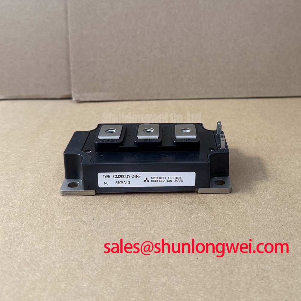
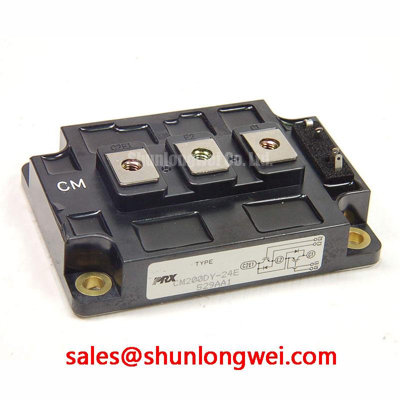
High-dynamics multi-axis CNC machines and robotic arm servo drives deployed at high-altitude manufacturing hubs encounter severe environmental stresses that rarely register on standard bench tests. When commissioning automated factory lines situated at elevations above 2,000 meters, terrestrial cosmic ray-induced neutron flux increases exponentially compared to sea-level baselines. In medium-voltage power stages, secondary atmospheric neutrons collide with the silicon lattice of the CM200DY-24E module, triggering localized charge generation inside the high-field depletion layer. This event can precipitate Single Event Burnout (SEB), a catastrophic, unclampable breakdown that destroys the internal planar gate structure in picoseconds without prior thermal warning.
The Mitsubishi Electric CM200DY-24E is officially rated for a maximum collector-emitter voltage of VCES = 1200 V (Official Datasheet Specification) and a continuous DC collector current of IC = 200 A (Official Datasheet Specification). Under high-altitude conditions, relying on the nominal 1200 V rating without adequate DC-bus voltage headroom derating invites unexplainable inverter tripping and field attrition. Industrial reliability modeling indicates that the failure-in-time (FIT) rate caused by SEB scales exponentially with the applied stationary electric field across the reverse-biased collector-emitter junction. To maintain high system availability in robotic controllers, field service engineers routinely enforce an operational continuous DC-bus voltage limit between 600 V and 750 V (General Industry Design Consideration for 1200V Class Silicon). This design margin suppresses cosmic-ray FIT rates to negligible levels, ensuring continuous five-axis milling runs without sporadic overvoltage shoot-through.
When triaging a blown servo axis cabinet on the plant floor, technicians must verify whether failure resulted from an SEB event or conventional thermal-avalanche breakdown. First, disconnect the module completely from the intermediate DC link and three-phase motor lines. Using a high-precision digital multimeter in diode-check mode, measure across collector-emitter terminals C1-E2 and C2E1-E2. A dead short (reading < 0.1 Ω) on a single half-bridge switch with clean, un-discolored baseplate nickel plating typically points to an instantaneous localized dielectric rupture rather than long-term thermal runaway. For root-cause isolation techniques, consult the comprehensive Field Engineer’s Handbook for standardized failure analysis methodologies.
| Parameter | Datasheet / Engineering Value | Condition / Designation |
|---|---|---|
| Collector-Emitter Voltage (VCES) | 1200 V | Gate-Emitter shorted (Official Datasheet Specification) |
| Collector Current (IC) | 200 A | Continuous DC (Official Datasheet Specification) |
| Pulsed Collector Current (ICM) | 400 A | Pulse rating, tp = 1 ms (Official Datasheet Specification) |
| Maximum Power Dissipation (PC) | 1500 W | TC = 25°C (Official Datasheet Specification) |
| Isolation Voltage (Viso) | 2500 Vrms | Main terminal to baseplate, AC 1 min (Official Datasheet Specification) |
| Saturation Voltage (VCE(sat)) | 3.5 V (Max) | IC = 200 A, VGE = 15 V (Official Datasheet Specification) |
| Gate Leakage Current (IGES) | 0.5 µA (Max) | VGE = 20 V, VCE = 0 V (Official Datasheet Specification) |
| Main Terminal Hardware | M6 Screws | Torque: 1.96 to 2.94 N·m (Official Datasheet Specification) |
High-Frequency Commutation Loop Inductance Minimization in High-Power Arrays
Rapid acceleration and sudden emergency braking in multi-axis CNC spindles generate steep current transients (di/dt) exceeding 2500 A/µs during IGBT turn-off transitions. In such high-stress commutation loops, any parasitic stray inductance (Lσ) residing in the laminated DC busbars or terminal screw interfaces converts magnetic energy directly into an overvoltage voltage spike that superimposes onto the nominal DC-bus voltage. According to basic inductive voltage response principles, the peak collector-emitter transient voltage equals the sum of the DC-link voltage and the product of total stray loop inductance and the turn-off di/dt rate. If the total commutation inductance is unmanaged, turn-off transient spikes can exceed the 1200 V ceiling of the CM200DY-24E, triggering unrecoverable breakdown across the primary chip termination ring.
To restrict commutation loop inductance below the target boundary of 25 nH (General Industry Design Consideration for high-speed industrial drives), drive designers implement low-profile, multi-layer planar busbar architectures. Symmetrical copper laminations separated by thin, high-dielectric-strength polyester films ensure that forward DC-plus and return DC-minus currents flow in exact antiparallel proximity, maximizing mutual electromagnetic cancellation. Low-inductance polypropylene film snubber capacitors must be bolted directly across the dual module's main C1 and E2 terminals using short, wide copper tabs rather than round leaded wire runs. In auxiliary power supplies or lower-current auxiliary braking circuits, the smaller-footprint CM15MD-12H provides an integrated power module topology to simplify internal layout routing.
⚠️ Field Alert: When retrofitting or replacing dual-pack modules in servo cabinets, never alter the factory-specified snubber mounting geometry or insert split spring washers beneath the high-current M6 main terminal busbar interfaces. Loose or uneven connections sharply elevate localized resistance and parasitic inductance. Fasten the main M6 electrical connections strictly within the specified range of 1.96 to 2.94 N·m (Official Datasheet Specification) using a calibrated torque screwdriver. Under-tightening introduces micro-arcing and overheating under pulse loads, while over-tightening fractures the internal copper-clad ceramic substrate.
During active switching transitions, free-wheeling diode recovery characteristics interact directly with drive loop dynamics. Designers and maintenance teams evaluating fault-clearing capabilities should review the ROHM Short-Circuit Withstand Time Guidelines to align gate protection trip thresholds, desaturation detection blanking times, and active clamping circuits against dead-short conditions.
High-Frequency Common-Mode Bearing Current and Cable Reflection Mitigation
Industrial multi-axis robotics installations often separate the central power conversion cabinet from remote servo motors using shielded cable runs stretching 30 to 100 meters across factory floors. The ultra-fast switching transitions of modern IGBT inverters produce steep dv/dt slew rates that interact with transmission line impedance mismatches. Because standard industrial cable wave impedance (typically 70 Ω to 100 Ω) differs substantially from the high surge impedance of motor stator windings (often > 1,000 Ω), voltage wave reflection occurs at the motor terminals. This transmission line reflection can double the peak line-to-line voltage, subjecting the motor turn-to-turn insulation to destructive surges near 2x the DC-bus voltage.
Simultaneously, high dv/dt switching steps inject high-frequency displacement currents through the parasitic capacitances between motor stator windings, rotor iron, and the grounded machine chassis. These common-mode currents seek a return path to the inverter DC link through the motor shaft and ball bearings. As charge accumulates across the non-conductive lubricating grease film, the breakdown threshold is reached, causing Electric Discharge Machining (EDM) currents. Over continuous operational cycles, this EDM arcing causes micro-crater fluting on bearing races, resulting in audible acoustic whining, mechanical vibration, and premature bearing destruction.
To eliminate these field failures, service specialists implement a multi-stage mitigation approach:
- dv/dt Output Chokes and Sine-Wave Filters: Installing passive LC or iron-core differential-mode chokes directly at the inverter output terminals attenuates voltage edge rates from over 5,000 V/µs down to manageable industrial levels below 500 V/µs (General Industry Design Consideration).
- Common-Mode Ferrite Absorbers: Threading all three motor phases (U, V, W) through high-permeability nanocrystalline or toroidal ferrite cores absorbs common-mode current spikes without attenuating fundamental drive torque frequencies.
- Shaft Grounding Rings and Hybrid Bearings: Fitting dynamic conductive microfiber grounding rings to CNC spindle shafts redirects residual displacement currents away from bearing assemblies directly to the grounded machine chassis.
- Enclosure Protection Verification: Ensure external terminal junction enclosures meet stringent ingress standards such as Ingress Protection (IP65 / IP67 / IP68) Dust & Water Proof Standards to prevent moisture or airborne metal shavings from degrading phase-to-ground creepage clearances.
For large gantry milling applications demanding higher sustained output current capacities beyond the 200 A capability of the CM200DY-24E, engineers frequently standardize on the higher-rated single-switch CM400HA-12E module to handle heavy mechanical load steps with elevated thermal margins.
Transient Thermal Impedance (Zth(j-c)) & Multi-Layer Foster/Cauer Modeling
High-speed pick-and-place robots and complex multi-axis milling operations subject the CM200DY-24E to severe, repetitive pulsed power overloads during rapid acceleration cycles. While steady-state thermal resistance Rth(j-c) dictates continuous dissipation limits, short-duration load bursts (e.g., 50 ms to 500 ms) are governed entirely by transient thermal impedance (Zth(j-c)). During brief peak-torque bursts, heat generated in the silicon junction cannot instantly diffuse across the internal solder layer, Direct Bonded Copper (DBC) ceramic substrate, and thick copper baseplate. Accurately predicting junction temperature (Tj) excursions during transient acceleration requires dynamic multi-layer thermal RC network modeling.
Engineers utilize multi-order Foster and Cauer equivalent RC circuits to mathematically model thermal diffusion paths. In a standard four-layer Foster model, transient thermal response over time follows the equation where transient thermal impedance Zth(j-c)(t) equals the summation of Ri × (1 - exp(-t / τi)), with each stage representing the thermal resistance Ri and thermal time constant τi of the silicon die, primary solder, DBC substrate, and module baseplate respectively (Engineering Calculation based on multi-order RC thermal networks). For the CM200DY-24E, total module power dissipation capacity is rated at PC = 1500 W at a case temperature of TC = 25°C (Official Datasheet Specification), operating within a continuous junction temperature range of Tj = -40 to +150 °C (Official Datasheet Specification).
💡 Pro Tip: During replacement procedures, baseplate thermal interface preparation is the single most critical factor determining module lifespan under pulsed duty. Follow these precise mechanical assembly steps:
- Clean the heatsink contact surface using isopropyl alcohol until free of debris, oxidation, and old grease. The heatsink surface flatness must remain within 50 µm over a 100 mm span, with a surface roughness of Rz ≤ 10 µm (General Industry Design Consideration).
- Apply a uniform 80 µm to 100 µm layer of high-conductivity thermal paste (minimum 2.5 W/m·K) across the module baseplate using a silk-screen printer or calibrated notched squeegee. Excess paste acts as a thermal insulator, while insufficient paste leaves micro air voids that trigger local thermal hot-spots.
- Mount the module onto the heatsink using M6 bolts. First, pre-tighten all corner bolts to 1/3 of the final torque in a diagonal crisscross sequence (1-4-2-3). Allow the thermal grease to settle for 5 minutes, then apply the final fastening torque of 1.96 to 2.94 N·m (Official Datasheet Specification) using a calibrated torque wrench.
Following this precise thermal mounting and screening procedure ensures that the CM200DY-24E maintains optimal thermal contact, keeping dynamic junction temperature swings safely within allowable reliability boundaries throughout heavy CNC machining and robotic automation cycles.