Content last revised on October 6, 2026
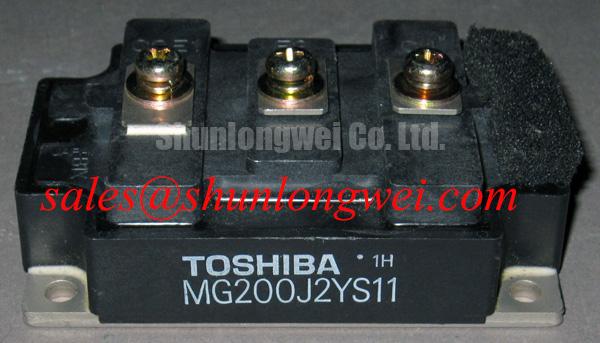
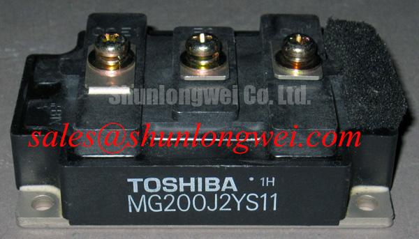
MG200J2YS11 Busbar Geometry and Transient Current Sharing
Measure the cold resistance between the DC bus terminals and the module connections, then compare the readings across equivalent paths before energizing the assembly. A loose joint, damaged conductor or unexpected short deserves investigation before a switching test. The MG200J2YS11 carries official ratings of 1200 V and 200 A; neither rating establishes the allowable operating current or voltage for an assembled converter without its thermal and switching conditions.
In a parallel installation, inspect the busbar runs from each module to the DC link and load. Unequal conductor lengths or connection geometry can create different impedances, so current may divide unevenly during a transition even if static measurements look similar. Design Consideration: Keep corresponding power paths geometrically symmetrical to reduce differences in parasitic inductance, then check individual current waveforms under the system’s intended switching conditions. A resistance check finds poor joints; it does not prove dynamic current sharing.
The gate paths need the same scrutiny. Trace each driver output and return on the equipment schematic, and inspect the physical routing rather than assuming that matching gate resistors produce matching waveforms. Mutual coupling with a high-current emitter path can disturb the voltage actually seen between gate and emitter. Where the installed module and driver expose a documented auxiliary emitter connection, evaluate that connection against the original pinout. Do not assign an undocumented terminal the role of a Kelvin emitter.
For static sharing, some IGBT operating regions exhibit a positive temperature coefficient of collector–emitter saturation voltage. That behavior is not a substitute for the MG200J2YS11 device curves or a measured current-sharing result. Check the applicable curves at the intended temperature and current before relying on them; use switching measurements to judge transient balance separately. In an industrial inverter welder or medium-frequency induction-heating supply, this distinction matters when assessing whether an existing parallel layout can accept a replacement module.
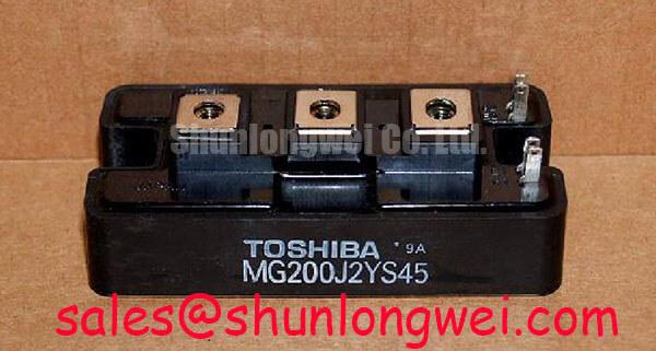
When evaluating another part, compare more than its nameplate ratings. MG200Q2YS40 is a related model to assess against the original schematic, terminal arrangement, mounting interface, gate-drive requirements and thermal limits. Its model relationship alone does not establish drop-in compatibility.
Gate-Drive Waveforms and Fault-Clearing Coordination
Probe gate-to-emitter voltage at the module terminals during a controlled switching test, and compare turn-on, turn-off and inactive-device waveforms with a known-good leg. Ringing or an unexpected gate excursion may point to return-path coupling, driver behavior or probe placement; establish which by tracing the loop and repeating the measurement with a suitable differential technique. A driver-board measurement taken far from the module can miss the voltage appearing at its terminals.
Design Consideration: Route the gate-drive return separately from the main current path where the documented terminal arrangement permits it. This reduces the chance that voltage developed across the power return will appear in the gate loop. Keep the drive loop compact to limit ringing, but select its final geometry and damping from measured switching behavior, driver capability and the equipment’s operating envelope—not from a generic resistor value.
Inspect the isolated driver supply while switching at the equipment’s demanding operating points. If the circuit uses a bootstrap supply, monitor the bootstrap capacitor voltage through its charging and discharging intervals and check the diode’s behavior during switching. Insufficient recharge or diode recovery effects can alter the applied gate voltage. Compare the observations with the installed driver’s design requirements before changing components. Check optocoupler or digital-isolator signals at both sides of the isolation boundary when common-mode switching noise is suspected; component common-mode transient immunity alone does not establish immunity for the assembled board.
Follow the schematic outward from the module to its supply and protection stages. A device such as MG100Q1ZS40 can be considered in a related system-topology review, but its function and suitability must be established from the particular circuit. Record which component supplies the DC link, which measures current and which commands shutdown. That record prevents a gate-drive symptom from being mistaken for a fault originating in an upstream stage.
Check the semiconductor fuse as part of the same fault-path review. Its clearing energy, expressed as I²t, must be evaluated against the available fault current and the limits of the components it protects. Design Consideration: A fast fuse and an electronic short-circuit detector address different portions of a fault event; neither should be assumed to protect the module on its own. The equipment designer must establish coordination from the fuse data, device limits, circuit impedance and measured or validated fault response.
MG200J2YS11 Thermal Interface and Mechanical Inspection
Inspect the mounted module for uneven seating, disturbed fasteners and thermal compound pushed into isolated patches around the baseplate. Those observations do not identify a failure by themselves, but they direct the next check: inspect the heatsink mating surface and mounting procedure before repeating a temperature test. The module’s 200 A current rating (Official Specification) does not guarantee that current in a cabinet whose thermal path is poorly assembled.
Design Consideration: Apply thermal interface material as a continuous, controlled layer that fills surface irregularities without creating excessive separation between mating surfaces. Examine the heatsink for damage or distortion and follow the mounting sequence and torque specified for the actual module and hardware. Do not infer a torque or grease thickness from the Toshiba Module package description; the mechanical drawing and assembly instructions govern those details.
⚠️ Field Alert: Isolate and verify the DC link is discharged before loosening module terminals or mounting hardware.
After assembly, log baseplate or heatsink temperature at a repeatable load point and compare it with the equipment’s established baseline. If temperature rises unexpectedly, check airflow, contact quality, load current and switching behavior rather than treating the interface material as the sole cause. In equipment that alternates between charging and discharging, repeated thermal excursions warrant review against the application’s thermal design; no operating-life figure follows from the module ratings alone.
Keep the electrical checks alongside the thermal record. A poor power connection can add local heating, while altered switching can increase module losses without a visible mounting defect. For a structured sequence of cold checks, waveform capture and fault isolation, use the Field Engineer’s Handbook alongside the equipment’s service documentation.
Desaturation Detection and Turn-Off Overvoltage
Capture the desaturation input, gate voltage and collector–emitter voltage during a controlled protection test; confirm that the driver detects the intended condition and that its shutdown response does not produce an excessive voltage peak. A desaturation indication should not be treated as proof of a failed module until the sensing path, blanking behavior, driver supply and power circuit have been checked. Likewise, a clean low-current switching trace does not establish behavior under a short-circuit event.
Short-circuit protection depends on the actual gate driver, fault type and device limits. The MG200J2YS11 voltage and current ratings supplied here do not specify a short-circuit withstand time or safe operating area, so a universal detection deadline cannot be assigned to it. Design Consideration: Review the driver’s desaturation threshold and response against the applicable device documentation and the equipment’s validated fault study, including faults present at turn-on and faults that develop while the device is conducting.
Turn-off speed presents a separate tradeoff. Rapid interruption of fault current can increase inductive overshoot in the power loop; a slower or staged turn-off may reduce that peak but must still clear the fault within the device’s validated limits. If the installed driver implements staged soft turn-off, verify its gate and collector–emitter waveforms in the complete assembly. Do not add a two-stage sequence solely because it appears in another converter design.
Inspect the DC-link layout and any snubber or metal-oxide varistor network shown on the equipment schematic. Minimize loop inductance where practical to suppress turn-off overshoot, then measure the peak against the operating DC-link voltage and the module’s 1200 V collector–emitter rating (Official Specification). An MOV’s clamping characteristic and energy duty need assessment in that circuit; its presence does not by itself demonstrate that repetitive switching peaks or fault transients remain within device limits. Close the fault review by checking the recorded peak voltage, gate response and fuse coordination against the system’s approved protection design.