
Content last revised on September 10, 2026
Toshiba MG200Q2YS40 Dual IGBT Module: Engineering Overview & Specs
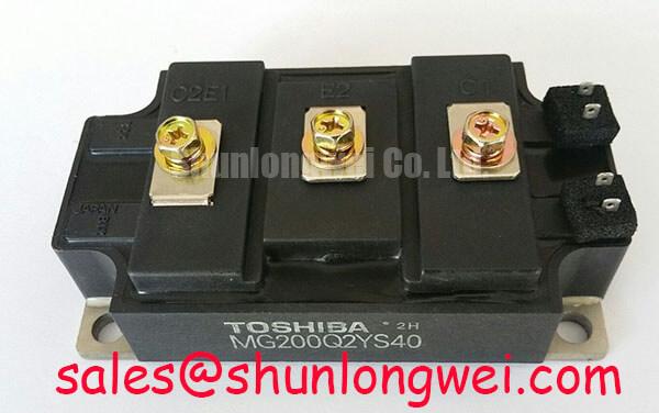
The Toshiba MG200Q2YS40 is an N-channel enhancement-mode half-bridge power semiconductor module designed for high-power switching and industrial motor control circuits. For 1200V motor control applications requiring low junction-to-case thermal resistance, the Toshiba MG200Q2YS40 provides 200A half-bridge switching capability.
Key Ratings: 1200V collector-emitter voltage | 200A continuous collector current | 0.096 °C/W transistor junction-to-case thermal resistance.
Engineering Highlights: Minimal switching power loss | Electrically isolated baseplate design.
How does the low junction-to-case thermal resistance impact cooling design in closed-chassis drives? The low thermal resistance of 0.096 °C/W allows system designers to minimize heat sink footprint while keeping peak junction temperatures safely within specified ratings during continuous 200A heavy-duty operation.
Key Parameter Overview
Decoding Specs for Enhanced Thermal & Electrical Performance
Below is a summary of the key electrical and thermal specifications for the MG200Q2YS40 based on official technical documentation.
| Parameter | Symbol | Test Conditions / Details | Value / Rating |
|---|---|---|---|
| Collector-Emitter Voltage | VCES | VGE = 0V, IC = 2.0mA | 1200V |
| Continuous Collector Current | IC | DC rating, Tc = 25°C | 200A |
| Collector-Emitter Saturation Voltage | VCE(sat) | IC = 200A, VGE = 15V (Typical) | 3.0V (Max 4.0V) |
| Fall Time | tf | Inductive load, Typical | 0.2 µs (Max 0.5 µs) |
| Reverse Recovery Time | trr | IF = 200A, VGE = -10V | 0.25 µs (Max 0.5 µs) |
| Transistor Thermal Resistance | Rth(j-c) | Junction to case (Transistor) | 0.096 °C/W |
| Diode Thermal Resistance | Rth(j-c) | Junction to case (Diode) | 0.25 °C/W |
| Isolation Voltage | VIsol | AC 1 minute, isolated terminals to baseplate | 2500V AC |
Download the MG200Q2YS40 datasheet for detailed specifications and performance curves.
Application Scenarios & Value
Achieving System-Level Efficiency in High-Power Motor Drives
Engineers designing high-power pulse-width modulation (PWM) power converters, variable frequency drives (VFDs), and uninterruptible power supplies (UPS) encounter severe thermal stresses under high current demand. In a 400V to 480V industrial AC motor drive, handling motor surge currents without exceeding the 150°C maximum junction temperature is a primary concern. The MG200Q2YS40 integrates two complete IGBT switches with anti-parallel fast recovery diodes into a single half-bridge package, eliminating external wiring parasitic inductance between half-bridge switches.
For systems with lower power demands, a lower current module such as the related MG150Q2YS50 offers a 150A rating, whereas higher throughput systems may evaluate options such as the related MG400Q2YS60A for handling up to 400A loads.
Technical & Design Deep Dive
Thermal Management and Low-Loss Switching Dynamics
The internal architecture of the MG200Q2YS40 utilizes an optimized silicon N-channel structure configured for rapid voltage-controlled gate turn-on and turn-off. With a typical turn-off fall time tf of 0.2 µs, switching energy losses are suppressed during high-frequency carrier modulation. Understanding these internal dynamics is essential when analyzing modern IGBT module architecture.
Thermal resistance acts like a highway bottleneck for heat flow: the lower the resistance value, the wider the highway. A junction-to-case thermal resistance Rth(j-c) of 0.096 °C/W allows thermal energy generated at the silicon die level to rapidly transfer to the module copper baseplate, enabling stable operation under tough duty cycles. For in-depth power converter thermal optimization strategies, refer to our detailed guide on 1200V IGBT industrial inverter optimization. Proper heat sink mounting torque (3.0 N·m) ensures flat physical interface contact, mitigating thermal breakdown risks detailed in our IGBT failure analysis technical reference.
External engineering resources on thermal resistance principles provide broader physics-based formulas for overall system heat balance calculations.
Frequently Asked Questions
Engineering Insights for Gate Drive & Thermal Design
What is the primary thermal resistance of the MG200Q2YS40 transistor? Junction-to-case thermal resistance is 0.096 °C/W.
What gate voltage specification is recommended for driving the MG200Q2YS40?
The absolute maximum gate-emitter voltage rating VGES is ±20V. For optimal saturation voltage performance (VCE(sat) typical 3.0V), a positive turn-on drive voltage of VGE = +15V is specified. A negative off-state gate bias (such as -5V to -10V) is recommended in high dV/dt environments to prevent accidental parasitic turn-on.
How does the 2500V AC isolation voltage rating assist mechanical layout?
The module features an electrically isolated copper baseplate capable of withstanding 2500V AC for 1 minute between the internal terminals and the metal mounting plate. This allows multiple power modules to be mounted onto a shared heatsink ground plane without requiring additional dielectric mica sheets, simplifying assembly layout.