Content last revised on September 10, 2026
Toshiba MG200Q2YS11 1200V 200A IGBT Module: Optimizing Efficiency in Industrial Power Conversion
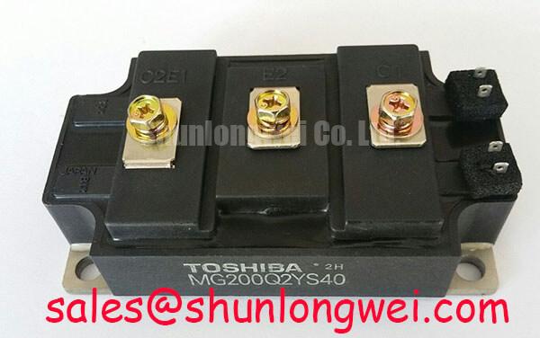
The Toshiba MG200Q2YS11 represents a high-performance dual IGBT module engineered to meet the rigorous demands of industrial power electronics, offering exceptional switching efficiency and thermal reliability for high-power applications. As a specialized dual-bridge solution, it integrates two N-channel IGBTs and two high-speed free-wheeling diodes into a single isolated package, simplifying system architecture while maintaining superior electrical integrity.
UVP Statement: This module provides a high-reliability switching core for industrial motor drives and uninterruptible power systems by balancing low saturation voltage with rapid switching characteristics. Top Specs: 1200V | 200A | 2500V AC Isolation. Key Benefits: Reduced conduction losses through optimized silicon design and simplified thermal management via its isolated baseplate. How does the low Vce(sat) of 3.0V (typ.) affect efficiency? It significantly lowers heat dissipation during high-load periods, allowing for smaller heatsink dimensions and improved power density. For industrial VFDs requiring high thermal margins, this 1200V 200A dual module is the optimal choice.
Key Parameter Overview
Decoding the Specs for Enhanced Thermal Reliability
To support engineering evaluation and procurement decisions, the following technical data is derived directly from authorized product documentation. These values represent the absolute maximum ratings and typical electrical characteristics essential for designing robust power stages.
| Technical Parameter | Specified Value / Condition | Design Advantage |
|---|---|---|
| Collector-Emitter Voltage (Vces) | 1200V | Ensures safety margins for 480V/600V AC lines |
| Collector Current (Ic) | 200A (Continuous @ Tc=25°C) | High-current throughput for heavy industrial loads |
| Saturation Voltage (Vce(sat)) | 3.0V (Typical) | Minimizes power loss during the "ON" state |
| Isolation Voltage (Visol) | 2500V AC (1 minute) | Compliance with industrial safety standards |
| Junction Temperature (Tj) | Up to +150°C | Reliable operation in high-ambient environments |
| Switching Times (tf) | 0.3µs (Typical Fall Time) | Supports high-frequency PWM for smooth control |
Application Scenarios & Value
Achieving System-Level Benefits in High-Frequency Power Conversion
The MG200Q2YS11 is primarily utilized in Variable Frequency Drives (VFD) and Solar Inverter topologies where high current density and thermal stability are non-negotiable. Consider a high-fidelity engineering scenario involving an industrial conveyor system: the primary challenge is managing the motor start-up surge current, which can reach several times the nominal rating. The 200A collector current rating of this module, combined with its robust SCSOA (Short Circuit Safe Operating Area), ensures the power stage survives these transients without degradation.
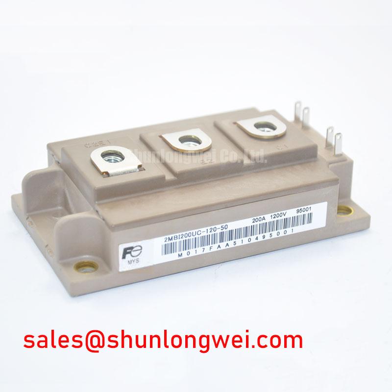
In the context of UPS (Uninterruptible Power Supply) systems, efficiency is critical for maintaining battery life and reducing cooling costs. By utilizing the MG200Q2YS11, engineers can leverage its low switching losses to operate at higher PWM frequencies, which in turn reduces the physical size of output filters and inductors. This is a classic example of how a component's electrical profile dictates the overall footprint of the system. For systems requiring a similar voltage class but different packaging footprints, the 2MBI200NB-120 offers an alternative configuration to consider during the evaluation phase.
Furthermore, this module is an ideal candidate for Welding Power Supply designs, where rapid current regulation and high-speed switching are essential for arc stability. The 2500V isolation voltage allows the power module to be mounted directly onto common heatsinks without additional insulation layers, improving thermal transfer efficiency (Rth). For designers scaling up to even higher power requirements, the SKM300GA123D provides an 1200V rating with a higher current handling capacity.
Technical & Design Deep Dive
Advanced Silicon Structure for Minimal Switching Loss
The MG200Q2YS11 utilizes a refined GTR (Giant Transistor) technology lineage transitioned into advanced IGBT silicon. One of the defining characteristics of this module is its optimized gate charge (Qg) requirement. A lower gate charge allows for the use of smaller, less expensive Gate Drive circuits while still achieving the fast transition speeds required to minimize switching energy (Eon/Eoff). This is analogous to a light switch with a very "crisp" action; the less time the switch spends between 'on' and 'off', the less energy is wasted as heat in the transition.
Reliability in harsh electromagnetic environments is further bolstered by the module's internal layout, which is designed to minimize stray inductance. In high-speed switching applications, stray inductance can lead to significant voltage spikes (V=L*di/dt) that threaten the Safe Operating Area (SOA). The MG200Q2YS11 addresses this by maintaining a compact internal busbar structure. When integrating this module, engineers should pay close attention to the Snubber Circuit design to further clamp these transients, ensuring long-term reliability even under full-load switching conditions.
FAQ
How does the Vce(sat) of 3.0V directly impact heatsink selection and overall system power density?
A Vce(sat) of 3.0V at 200A generates approximately 600W of conduction loss per switch at full load. This directly dictates the required Thermal Resistance of the heatsink to keep the junction temperature below 150°C. Lowering this loss through efficient component selection like the MG200Q2YS11 allows for more compact heatsink designs, thereby increasing total system power density.
What is the significance of the 2500V isolation voltage for multi-phase inverter designs?
The 2500V isolation rating ensures that the internal silicon is electrically isolated from the module's baseplate. This allows multiple MG200Q2YS11 modules to be mounted on a single grounded heatsink, reducing complexity and ensuring compliance with safety standards such as UL and IEC for industrial equipment.
How should the Gate Drive voltage be configured for optimal switching in the MG200Q2YS11?
For this specific module, a gate drive voltage of +15V for turn-on is recommended to ensure the IGBT is fully saturated, minimizing conduction losses. A negative bias (e.g., -5V to -10V) for turn-off is highly recommended to prevent parasitic turn-on caused by the Miller effect during high dV/dt transitions.
Can the MG200Q2YS11 handle inductive load switching without external protection?
While the module includes integrated high-speed free-wheeling diodes to handle inductive energy during turn-off, it is standard engineering practice to include a snubber capacitor across the C1 and E2 terminals to suppress voltage transients caused by DC-link busbar inductance.
From a strategic perspective, selecting the MG200Q2YS11 allows for a standardized approach to power stage design across multiple product lines, from 50kW to 150kW. By focusing on a module with proven thermal cycling capability and consistent electrical parameters, engineering teams can reduce validation time and accelerate the transition to high-efficiency power architectures. For further insights into maximizing module lifespan, refer to our guide on ensuring IGBT reliability.