


Content last revised on June 29, 2026
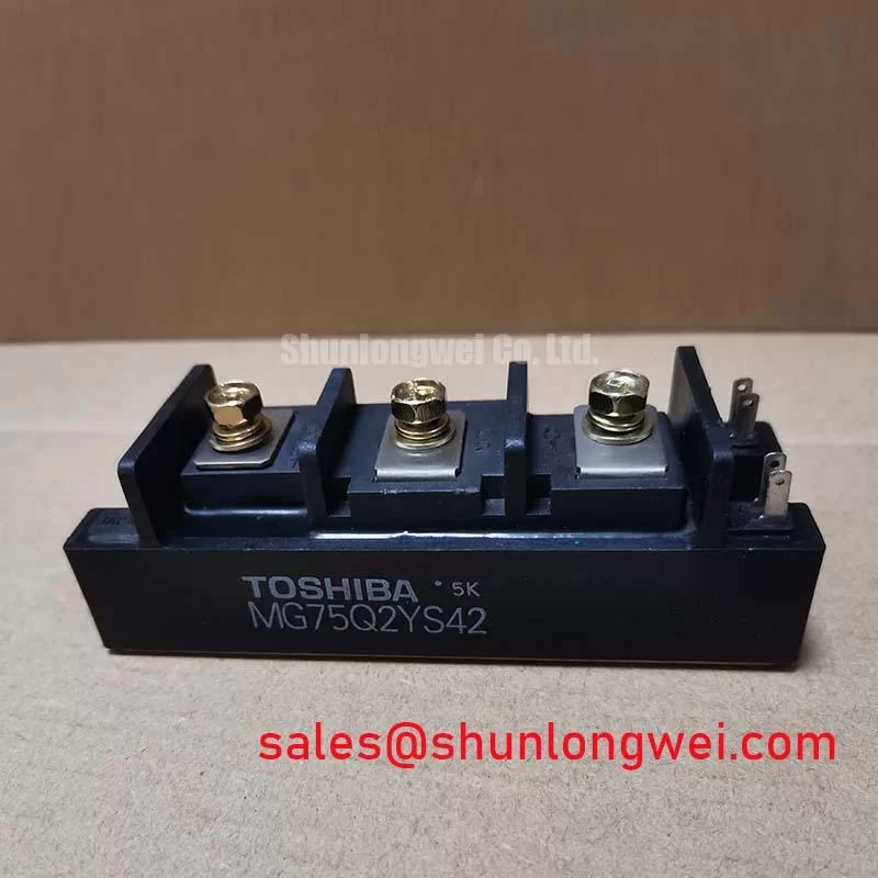
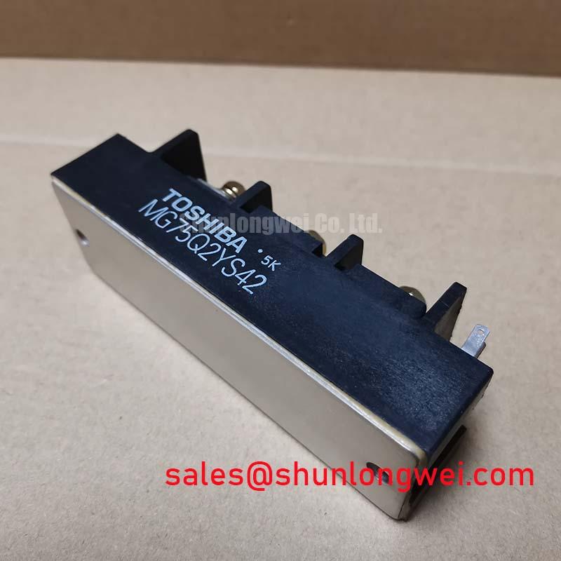
MG75Q2YS42 | 1200V 75A Dual IGBT Module | Technical Datasheet & Specs
Product Overview & Key Specifications
Engineered for Efficiency in High-Voltage Switching Applications
The MG75Q2YS42 is a 1200V, 75A dual IGBT module designed to deliver robust performance and high efficiency in demanding power conversion systems. It leverages proven NPT-IGBT technology to achieve a low collector-emitter saturation voltage (VCE(sat)), directly minimizing conduction losses and reducing thermal management requirements. How does this translate to better inverter design? By lowering the primary source of heat—conduction loss—it enables more compact, reliable, and energy-efficient systems. Its integrated half-bridge configuration simplifies the layout of inverter legs for applications like industrial motor drives and uninterruptible power supplies. For mid-power industrial drives where thermal budget is a primary constraint, the MG75Q2YS42's low VCE(sat) makes it a strategically sound choice.
- Core Specifications: 1200V | 75A | VCE(sat) 2.7V (typ)
- Key Benefit 1: Reduced power dissipation
- Key Benefit 2: Simplified thermal design
Key Parameter Overview
Decoding the Specs for Lower Conduction Losses
The technical specifications of the MG75Q2YS42 are optimized for performance and reliability in high-voltage environments. The parameters below highlight the module's capability to manage significant power loads while maintaining high operational efficiency, a critical factor in modern power electronics design. The low saturation voltage is particularly important for reducing heat generation under load.
| Parameter | Value | Conditions |
|---|---|---|
| Collector-Emitter Voltage (Vces) | 1200V | VGE = 0V |
| Gate-Emitter Voltage (VGES) | ±20V | |
| Collector Current (IC) | 75A | DC, Tc = 25°C |
| Collector Current (ICp) | 150A | 1ms Pulse |
| Collector-Emitter Saturation Voltage (VCE(sat)) | 2.7V (typ) / 3.25V (max) | IC = 75A, VGE = 15V |
| Collector Power Dissipation (PC) | 480W | Per IGBT |
| Operating Junction Temperature (Tj) | -40 to +150°C | |
| Isolation Voltage (Visol) | 2500V | AC, 1 minute |
Download the MG75Q2YS42 datasheet for detailed specifications and performance curves.
Application Scenarios & Value
System-Level Benefits in Industrial Power Conversion
The MG75Q2YS42 is engineered for applications where efficiency and reliability are paramount. Its robust 1200V rating provides the necessary design margin for inverters connected to 380V and 480V three-phase AC lines, making it an ideal component for a wide range of industrial equipment.
Consider the design of a 30 kW Variable Frequency Drive (VFD). A primary engineering challenge is managing the heat generated by the power stage to ensure a long operational life and maintain system stability. The MG75Q2YS42 directly addresses this. Its typical VCE(sat) of 2.7V minimizes the energy converted into heat during conduction phases. Think of VCE(sat) as a small, unavoidable tax on the energy passing through the switch; a lower tax means less waste. This reduction in wasted energy not only boosts the VFD's overall efficiency but also allows engineers to specify smaller, more cost-effective heatsinks, potentially reducing the overall size and bill of materials for the final product. The integrated half-bridge configuration further simplifies the PCB layout and bus bar design, accelerating development time. For systems that demand higher power output, the related MG150Q2YS50 offers double the current handling capability in a similar package footprint.
Technical Deep Dive
A Closer Look at NPT-IGBT Structure and Efficiency Gains
The performance characteristics of the MG75Q2YS42 are rooted in its Non-Punch-Through (NPT) IGBT technology. Unlike earlier punch-through (PT) designs, NPT devices feature a thicker, lightly doped n-drift region. This structural difference yields several key engineering advantages relevant to industrial applications. Primarily, it results in a positive temperature coefficient for the collector-emitter saturation voltage. This characteristic is highly beneficial when paralleling modules for higher current capacity, as it naturally helps balance current sharing between the devices and prevents thermal runaway in one of the modules.
Furthermore, the NPT structure provides a wider, more robust Safe Operating Area (SOA), particularly under short-circuit conditions. This inherent ruggedness gives designers greater confidence in the module's ability to withstand fault conditions commonly encountered in industrial environments, such as motor stalls or output short-circuits. While this module provides a solid foundation, achieving optimal performance always requires a well-designed gate drive circuit to control switching behavior effectively.
Frequently Asked Questions (FAQ)
Engineering Q&A: Performance and Integration
How does the 2.7V VCE(sat) of the MG75Q2YS42 influence heatsink selection for a VFD application?
A lower VCE(sat) directly reduces conduction power loss (P_loss = VCE(sat) * Ic). With less heat to dissipate, engineers can often select a heatsink with a higher thermal resistance (a smaller or less complex design), reducing system cost, weight, and volume without compromising on the target junction temperature.
What is the primary benefit of the MG75Q2YS42's half-bridge (2-in-1) configuration for an inverter designer?
The primary benefit is design simplification. It integrates two series-connected IGBTs, forming a complete inverter leg in a single package. This minimizes stray inductance between the switches compared to using two discrete modules, reduces component count, and simplifies the bus bar and PCB layout, leading to a more compact and electrically efficient design.
Does the 2500V RMS isolation rating of the MG75Q2YS42 eliminate the need for insulating washers during assembly?
Yes, the module's baseplate is electrically isolated from the internal semiconductor chips and terminals. This high isolation voltage allows direct mounting onto a grounded chassis or heatsink without the need for additional thermal insulating pads (like mica or silicone), which simplifies the assembly process and can improve thermal transfer.
What are the key parameters to consider when evaluating the MG75Q2YS42 as a replacement for another 1200V IGBT module?
Beyond the primary ratings of Vces (1200V) and Ic (75A), critically compare the VCE(sat) at your typical operating current, the total switching energy (Eon + Eoff), and the thermal resistance from junction to case (Rth(j-c)). Also, verify that the package dimensions and terminal layout are compatible with your existing design.
Strategic Fit for Industrial Upgrades
For engineering teams tasked with improving the efficiency and power density of existing industrial drive or UPS platforms, the MG75Q2YS42 presents a compelling component choice. Its balance of voltage overhead, current capacity, and, most importantly, low conduction losses offers a direct path to achieving tangible gains in system performance and thermal stability. Integrating this module can be a key step in meeting next-generation energy efficiency standards and reducing long-term operational costs for the end-user. For a deeper understanding of these parameters, refer to this guide on decoding IGBT datasheets.