


Content last revised on February 4, 2026
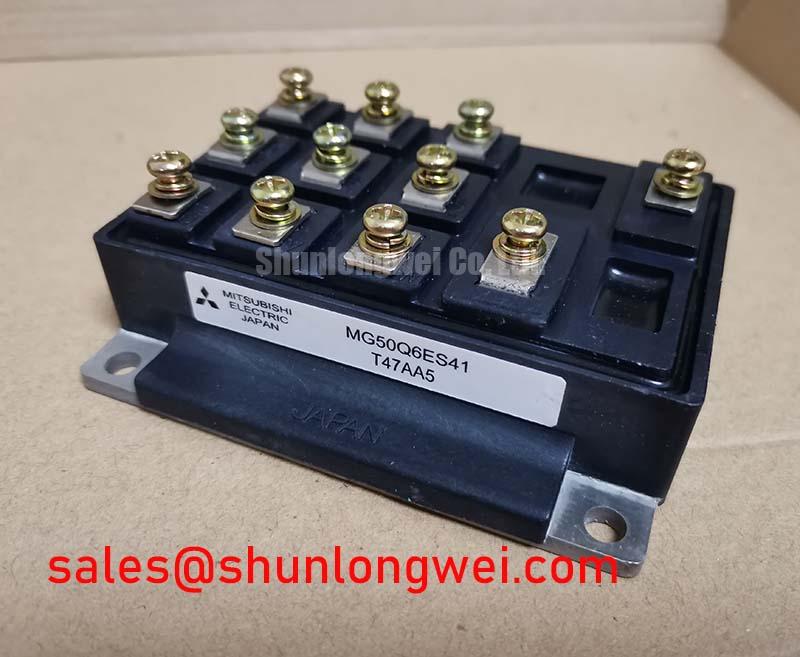
MG50Q6ES41 Datasheet, Specs & Analysis: A 1200V/50A IGBT for Efficient Motor Drives
An Engineering Overview
Optimizing Performance in High-Speed Power Switching
The Toshiba MG50Q6ES41 is a high-speed Silicon N-Channel IGBT module architected as a complete three-phase inverter bridge. It delivers a strategic balance of switching efficiency and robust power handling for demanding industrial applications. With core specifications of 1200V | 50A | VCE(sat) 2.7V (typ.), this module provides two critical engineering benefits: significantly reduced switching losses and a simplified system design. This component directly addresses the need for creating more efficient and compact power conversion systems without compromising on reliability. For industrial motor drives up to 15 kW requiring a blend of performance and integration, the MG50Q6ES41's balanced profile makes it a highly effective choice.
Application Scenarios & Value
Achieving System-Level Benefits in Industrial Automation
The primary value of the MG50Q6ES41 is realized in the design of small- to medium-power Variable Frequency Drives (VFDs) and servo systems. A common engineering challenge in this space is maximizing power density while controlling system cost and thermal load. The integrated "six-pack" configuration of the MG50Q6ES41, which includes six IGBTs and six co-packaged free-wheeling diodes (FWDs), is the solution. This integration dramatically reduces the bill of materials (BOM), simplifies the PCB layout, and minimizes parasitic inductance associated with discrete components, leading to cleaner switching and improved EMI performance.
Consider the design of a 10 kW VFD for a conveyor belt system. The MG50Q6ES41's high-speed switching characteristics (typical turn-off time of 1.0µs) enable the use of higher Pulse Width Modulation (PWM) frequencies. This allows engineers to specify smaller, less expensive magnetic components and output filters, directly shrinking the overall physical volume of the drive. The module's robust 1200V rating provides essential safety headroom for operation on 400V or 480V AC lines, ensuring resilience against transient voltage spikes common in industrial environments. For systems demanding higher current capacity, the related CM100DY-24H offers a 100A rating within a similar voltage class.
Key Parameter Overview
A Functional Breakdown of Core Specifications
The technical specifications of the MG50Q6ES41 are tailored for balanced performance in switching applications. The parameters are organized below by their functional role in a power system design.
| Functional Grouping: Key Specifications | |
|---|---|
| Absolute Maximum Ratings |
|
| Static Electrical Characteristics (Tj=25°C) |
|
| Dynamic Electrical Characteristics (Tj=125°C) |
|
| Thermal and Mechanical |
|
Download the MG50Q6ES41 datasheet for detailed specifications and performance curves.
Technical Deep Dive
Analyzing the Trade-off Between Conduction and Switching Losses
A successful power stage design hinges on managing the interplay between conduction and switching losses, a core consideration when evaluating the MG50Q6ES41. This module's specifications provide the data needed to optimize this balance for target applications. What is the primary benefit of its high-speed design? Reduced switching losses and smaller system magnetics.
The Collector-Emitter Saturation Voltage (VCE(sat)) of 2.7V at 50A is the primary determinant of conduction losses. Think of this as the "pressure drop" across the switch when it's fully on; a lower VCE(sat) means less power is wasted as heat during the on-state. The MG50Q6ES41 offers a solid VCE(sat) value for its class, ensuring conduction losses are kept within a manageable range for efficient operation. For a detailed analysis of this parameter, engineers can refer to resources explaining VCE(sat) calculations.
Conversely, Switching Loss is determined by parameters like turn-on (ton) and turn-off (toff) times. These losses occur during the brief transition between the on and off states. The MG50Q6ES41's fast switching times (e.g., toff of 1.0µs) are crucial for reducing this type of loss, especially as PWM frequencies increase. The energy lost during each switch is analogous to the effort required to open and close a heavy, spring-loaded door; doing it faster and more efficiently minimizes energy waste over many cycles. A deeper understanding of these concepts can be found in guides covering VCE(sat) and Eon/Eoff for optimal efficiency.
Frequently Asked Questions (FAQ)
How does the VCE(sat) of the MG50Q6ES41 influence thermal design?
The VCE(sat) of 3.3V (max) at 50A directly dictates the conduction losses (P_cond = VCE(sat) * Ic). This value, combined with the thermal resistance (Rth(j-c)) of 0.28°C/W, allows an engineer to precisely calculate the junction temperature rise. A well-defined VCE(sat) enables more accurate heatsink selection, preventing over-engineering and helping to manage the overall system's thermal budget and physical size.
What is the significance of the integrated Free-Wheeling Diodes (FWDs) in this module?
The co-packaged FWDs are critical for inductive load applications like motor drives. When an IGBT turns off, the current in the motor winding cannot stop instantly. The FWD provides a safe path for this "freewheeling" current, protecting the IGBT from a potentially damaging overvoltage. The FWDs in the MG50Q6ES41 are optimized to work with the IGBTs, ensuring reliable commutation and managing reverse recovery losses, a key aspect of overall inverter efficiency.
Is this module suitable for parallel operation to achieve higher current?
The datasheet for the MG50Q6ES41 does not provide specific guidance or matched parameters for paralleling. While possible in theory, successfully paralleling IGBT modules requires careful consideration of gate drive design, busbar layout symmetry, and thermal balancing to ensure equal current sharing. Without manufacturer-specified matching, engineers should proceed with caution and conduct extensive testing. For applications requiring more than 50A, selecting a single, higher-rated module like the BSM100GB120DN2K is often a more reliable and straightforward design path.
Engineering Next Steps
The MG50Q6ES41 presents a compelling solution for engineers developing efficient and power-dense industrial converters. Its integrated design and balanced loss characteristics offer a clear path to reducing system complexity and improving performance. To further your evaluation, the next logical step is to download the full datasheet to analyze its performance curves under your specific operating conditions. This data will be crucial for conducting thermal simulations and validating its suitability for your application's unique load profile and lifecycle requirements.