


Content last revised on February 3, 2026
The MG100J7CSAOA: An In-Depth Engineering Review of the 600V/100A 7-in-1 GTR Module
Product Overview: A 7-in-1 Module for Efficient Power Conversion
Engineered for Integrated Motor Drives and Switching Applications
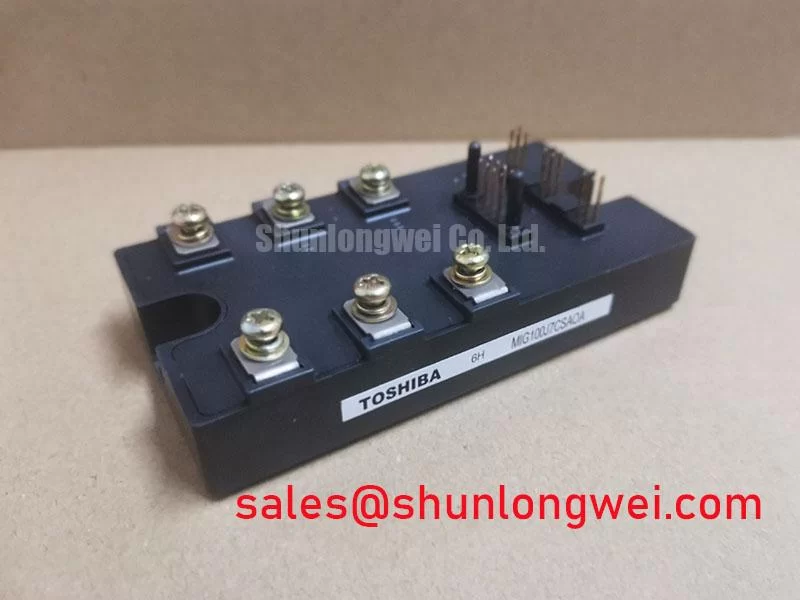
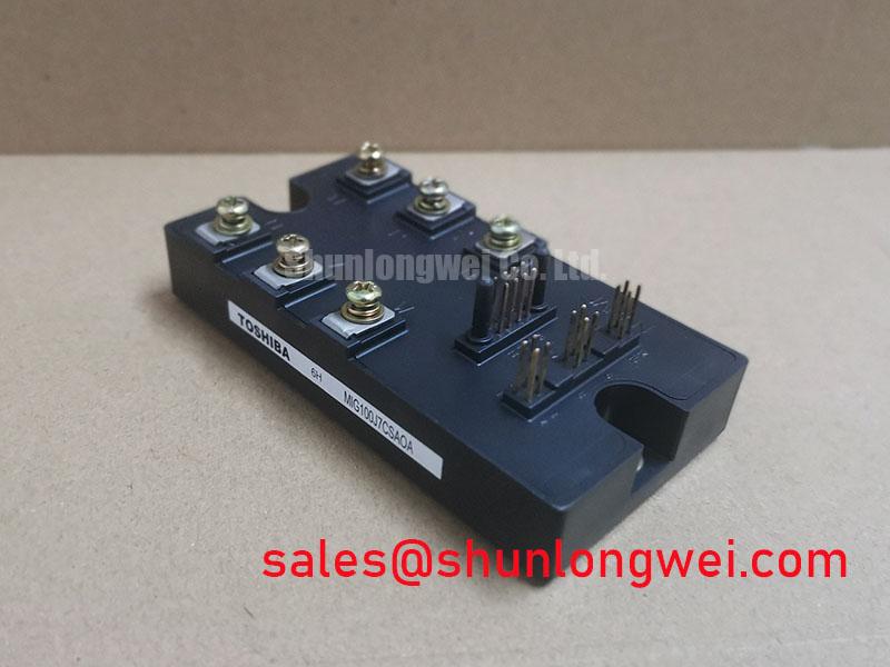
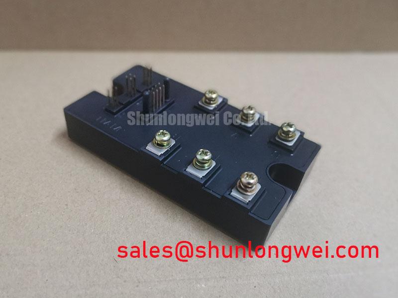
The Toshiba MG100J7CSAOA is a 600V, 100A GTR (Giant Transistor) module that integrates seven N-channel IGBTs into a single, thermally efficient package. It is engineered to balance switching speed and conduction characteristics for high-performance power systems. With key specifications of 600V | 100A | t_f 0.5 µs (max), this device offers significant benefits, including reduced switching losses and simplified system assembly. It directly addresses the engineering need for a compact power stage in modern motor drives. For 200-240V motor drives requiring a compact, all-in-one power stage, the MG100J7CSAOA offers a practical balance of integration and switching performance.
Key Parameter Overview
Decoding the Specs for Efficient Power Conversion
The electrical and thermal characteristics of the MG100J7CSAOA are foundational to its performance in demanding applications. The parameters below are derived from the official specification sheet and are critical for accurate system modeling, thermal design, and performance prediction.
| Absolute Maximum Ratings (T_c = 25°C) | |
|---|---|
| Collector-Emitter Voltage (V_CES) | 600 V |
| Gate-Emitter Voltage (V_GES) | ±20 V |
| Collector Current (DC) (I_C) | 100 A |
| Collector Current (Pulsed) (I_CP) (1ms) | 200 A |
| Collector Power Dissipation (P_C) | 300 W |
| Junction Temperature (T_j) | 150 °C |
| Isolation Voltage (V_isol) (AC, 1 min.) | 2500 V |
| Electrical Characteristics (T_j = 25°C unless otherwise specified) | |
| Collector-Emitter Saturation Voltage (V_CE(sat)) @ I_C = 100A | 2.5 V (max) |
| Fall Time (t_f) @ I_C = 100A | 0.5 µs (max) |
| Diode Reverse Recovery Time (t_rr) @ I_F = 100A | 0.3 µs (max) |
Application Scenarios & Value
System-Level Benefits in Motor Control and Power Conversion
The MG100J7CSAOA is best suited for high-frequency power conversion systems operating on 200-240V AC lines. Its architecture provides tangible value in applications such as industrial Variable Frequency Drives (VFDs), servo drives, and uninterruptible power supplies (UPS).
Consider the design of a compact VFD for a 15 kW motor. A key challenge is managing heat in a small enclosure. The MG100J7CSAOA's fast switching characteristics, specifically its 0.5 µs maximum fall time, directly reduce switching losses. This allows engineers to either increase the PWM frequency to reduce the size of magnetic components or to operate with a smaller heatsink at standard frequencies, both of which contribute to a higher power density. The integrated 7-in-1 configuration, which typically includes a three-phase inverter bridge and a brake chopper, drastically simplifies the power stage layout, reduces parasitic inductance, and shortens the assembly process. What is the primary benefit of its 7-in-1 design? It simplifies system assembly and reduces component count.
While this module is optimized for 100A applications, for lower power requirements or designs benefiting from integrated gate drivers, the related MIG50Q7CSAOX presents an alternative within a more integrated IPM format.
Frequently Asked Questions
Engineering Inquiries on the MG100J7CSAOA
How does the 7-in-1 configuration of the MG100J7CSAOA benefit a VFD design?
The integration of seven IGBTs into a single module simplifies the design of a standard three-phase inverter with an included brake chopper circuit. This reduces the bill of materials (BOM), minimizes PCB footprint, lowers assembly complexity, and can improve reliability by reducing the number of discrete components and interconnections.
What is the significance of the 0.5 µs fall time (t_f) for system efficiency?
The fall time is a major component of switching loss, which becomes increasingly critical at higher PWM frequencies. A fast fall time of 0.5 µs means the IGBT transitions from its on-state to its off-state very quickly, minimizing the duration where both high voltage and high current are present simultaneously. This directly reduces the energy dissipated as heat during each switching cycle, leading to higher overall inverter efficiency.
Given the V_CE(sat) of 2.5V, what is the best way to manage conduction losses?
While the 2.5V VCE(sat) is a key factor in conduction losses, effective thermal management is paramount. The primary strategy is to ensure a low-resistance thermal path from the module's baseplate to the heatsink. This involves using a high-quality thermal interface material (TIM) and applying the recommended mounting torque of 3 N·m to guarantee optimal contact and heat transfer. For a deeper understanding of thermal design, refer to our guide on mastering IGBT thermal management.
Technical Deep Dive
Analyzing the Interplay of VCE(sat) and Switching Speed for Loss Reduction
The design of any power converter involves a fundamental trade-off between conduction losses and switching losses. The MG100J7CSAOA's specifications illustrate a deliberate balance optimized for moderate to high-frequency applications. Its V_CE(sat) of 2.5V at 100A defines the steady-state power dissipation, while its sub-microsecond switching times (t_f = 0.5 µs, t_rr = 0.3 µs) govern dynamic losses. What is the impact of fast switching on design? It enables more compact systems by reducing cooling requirements.
To put this in perspective, think of the IGBT as a heavy steel door. Conduction loss, dictated by V_CE(sat), is like the constant force needed to hold the door fully open against a spring. Switching loss, on the other hand, is the burst of energy you expend to physically open or close that door. If you only open the door once a day, that effort is negligible. But in a high-frequency VFD, you are swinging that heavy door back and forth thousands of times per second (the PWM frequency). The MG100J7CSAOA's fast switching times are akin to having powerful, well-oiled hinges that move the door with minimal effort, ensuring the energy spent in motion (switching) doesn't overwhelm the energy spent holding it open (conduction). This balance is crucial for achieving high system efficiency.
For your next 240V drive design, evaluating the MG100J7CSAOA's performance characteristics provides a clear path to a more compact and efficient power stage. Review the datasheet and consider how its integrated topology can streamline your development process and help you meet stringent efficiency targets.