


Content last revised on March 30, 2026
FD200R12KE3 IGBT Module: Datasheet Analysis for 1200V Drives
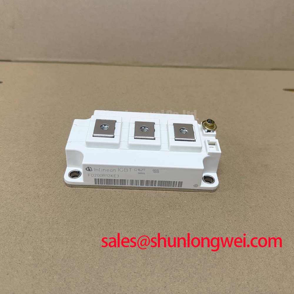
Engineered for high-frequency power conversion, the Infineon FD200R12KE3 IGBT module minimizes system-level losses using proven TRENCHSTOP™ IGBT3 technology. It provides a robust foundation for building thermally stable and efficient inverters.
Top Specs: 1200 V | 200 A | VCE(sat) 1.70V (typ.)
Key Benefits: Optimized for low switching losses. High thermal conductivity.
At the core of the FD200R12KE3's performance is the balance it strikes between conduction and switching losses, a critical factor for engineers designing high-frequency systems. The TRENCHSTOP™ IGBT3 technology achieves a low collector-emitter saturation voltage (VCE(sat)) without compromising its performance at switching frequencies common in motor drives and solar inverters, ensuring a lower total power loss across the operational cycle.
Operational Contexts Where Efficiency is Paramount
The technical specifications of the FD200R12KE3 translate directly into tangible benefits across several demanding power conversion applications. Its architecture is specifically tailored for systems where minimizing energy waste is a primary design goal. By integrating this module, engineers can achieve higher system efficiency, reduce the size and cost of cooling hardware, and improve the overall power density of the final product.
- Motor Drives: In Variable Frequency Drives (VFDs) and servo applications, the module's low switching losses enable higher PWM frequencies. This leads to reduced motor ripple current, lower audible noise, and more precise motor control, which are vital for robotics, CNC machinery, and industrial automation.
- Solar Inverters: The high efficiency facilitated by the TRENCHSTOP™ IGBT3 technology is critical for maximizing the energy harvest in photovoltaic systems. Lower power dissipation means more generated power is delivered to the grid, improving the return on investment for solar installations.
- Uninterruptible Power Supplies (UPS): For commercial and industrial UPS systems, the module's reliability and efficiency ensure minimal energy is wasted during standby and active operation, contributing to a lower total cost of ownership.
For drive systems up to ~90 kW requiring minimal derating at higher ambient temperatures, the FD200R12KE3's low Rth(j-c) of 0.072 K/W per IGBT makes it a thermally superior choice.
Comparative Analysis for Informed Engineering Decisions
To support your design evaluation process, this section provides a factual comparison based on publicly available datasheet parameters. This data is intended to help engineers assess how the FD200R12KE3 fits within the landscape of similar power modules. Note that performance in any specific application depends on a multitude of factors including gate drive design, thermal management, and operating frequency.
When evaluating alternatives, it is crucial to look beyond a single parameter. For instance, while one device may offer a slightly lower VCE(sat), another might provide superior switching performance or a more robust Safe Operating Area (SOA). For systems requiring a higher current rating within the same voltage class, the FF300R12KE3 is a related component to consider for evaluation.
Strategic Advantages in Energy-Conscious System Design
The adoption of advanced IGBT technologies like the TRENCHSTOP™ IGBT3 found in the FD200R12KE3 is a direct response to global trends toward greater energy efficiency and power density. Regulations and market demands are pushing for power electronics that waste less energy, and this module is a key enabler for meeting those targets. Systems built with this component can achieve higher efficiency ratings, which is not only an environmental benefit but also a significant competitive advantage. A more efficient inverter runs cooler, which can lead to extended component lifetime and greater system reliability, ultimately reducing maintenance costs and downtime for the end-user.
A Granular Look at Key Performance Parameters
Understanding the core specifications is fundamental to leveraging this module's full potential. The following table highlights key parameters from the FD200R12KE3 datasheet, organized by functional category. For a complete list of specifications and characteristic curves, please Download the Datasheet.
Parameter Interpretation
Collector-Emitter Saturation Voltage (VCE(sat)): With a typical value of 1.70V at nominal current (25°C), this parameter directly impacts conduction losses. A lower VCE(sat) means less power is dissipated as heat when the IGBT is fully on, a critical factor for overall system efficiency, particularly in applications with high duty cycles.
Thermal Resistance, Junction-to-Case (Rth(j-c)): The Rth(j-c) for the IGBT is specified at 0.072 K/W. This value acts like a bottleneck measurement for heat flow; a lower number indicates more efficient heat transfer from the silicon die to the module's baseplate. This superior thermal pathway simplifies heatsink design and allows the device to run cooler under heavy loads, enhancing long-term reliability.
| Parameter | Symbol | Condition | Value |
|---|---|---|---|
| Maximum Ratings | |||
| Collector-Emitter Voltage | V_CES | 1200 V | |
| Continuous Collector Current | I_C | T_C = 80°C | 200 A |
| Repetitive Peak Collector Current | I_CRM | t_p = 1 ms | 400 A |
| Operating Junction Temperature | T_vj op | -40 to +150 °C | |
| IGBT, Inverter - Characteristic Values | |||
| Collector-Emitter Saturation Voltage | V_CE sat | I_C = 200 A, V_GE = 15 V, T_vj = 25°C | 1.70 V (typ.) |
| Total Switching Energy | E_ts | I_C = 200 A, V_CE = 600 V, V_GE = ±15 V, R_G = 3.6 Ω | 33.00 mJ (typ.) |
| Thermal Characteristics | |||
| Thermal Resistance, Junction to Case | R_thJC | per IGBT | 0.072 K/W |
| Thermal Resistance, Junction to Case | R_thJC | per Diode | 0.12 K/W |
Inside the TRENCHSTOP™ IGBT3: A Focus on Loss Minimization
The Infineon FD200R12KE3 module integrates TRENCHSTOP™ IGBT3 and Emitter Controlled Diode technology, a combination engineered to reduce total power losses. What is the primary benefit of TRENCHSTOP IGBT3? It significantly lowers VCE(sat) for reduced conduction losses while maintaining fast and soft switching behavior. This "soft" switching characteristic of the integrated freewheeling diode is crucial for mitigating electromagnetic interference (EMI), which can simplify the design and reduce the cost of filtering circuitry required to meet regulatory standards. The balance achieved between low conduction losses and controlled switching losses makes this module highly effective in modern inverter designs. For a deeper understanding of IGBT characteristics, explore our guide on decoding IGBT datasheets.
Deployment Snapshot: Enhancing Drive Performance
A mid-sized European manufacturer of packaging machinery sought to upgrade their primary servo drive to reduce its physical footprint and improve energy efficiency. Their existing design used older generation IGBTs that required a bulky and expensive heatsink to manage thermal loads. By redesigning their 75 kW inverter stage around the FD200R12KE3, they were able to achieve a 15% reduction in total power losses. This improvement allowed for the use of a smaller, more cost-effective cooling solution, contributing to a 10% reduction in the drive's overall enclosure size and helping their product meet stricter energy efficiency standards.
Frequently Asked Technical Questions
1. How does the EconoDUAL™ 3 housing benefit my design?
The EconoDUAL™ 3 housing is an industry-standard footprint known for its reliability and ease of integration. It features a robust mechanical design with screw terminals for secure power connections and an isolated baseplate, which simplifies mounting to a heatsink and ensures high electrical insulation. This standardization facilitates easier second-sourcing and simplifies the overall mechanical layout of the power cabinet.
2. What are the key considerations for the gate drive circuit for the FD200R12KE3?
To achieve the specified low switching losses and ensure safe operation, the gate drive circuit is critical. Based on the datasheet, a gate voltage of +15V for turn-on and -15V for turn-off is recommended. The gate resistor (RG) value directly influences the switching speed and should be selected carefully to balance efficiency against voltage overshoots and EMI. A value of 3.6 Ω is used for datasheet characterization. Implementing a robust gate driver with sufficient current capability and low parasitic inductance is essential for reliable performance.
For more detailed technical information or to discuss your specific application needs, please contact our engineering support team for assistance.