

Content last revised on October 31, 2026
SKM200GAH126DKLT Identification and Replacement Checks
- Isolate the power stage, discharge stored energy using the equipment procedure, and verify absence of voltage before accessing the module terminals.
- Compare cold collector–emitter and gate–emitter measurements with an equivalent disconnected channel, accounting for parallel circuit paths.
- Inspect terminal seating, baseplate contact, and heatsink condition before disturbing the existing mechanical assembly.
- Match the complete SKM200GAH126DKLT designation to the equipment bill of materials and terminal drawing.
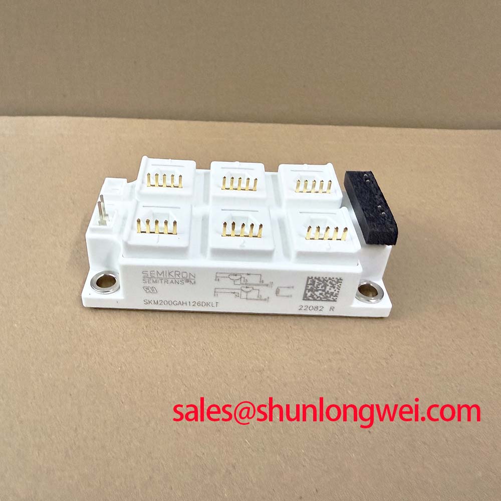
The Semikron SKM200GAH126DKLT is a 1200 V, 200 A IGBT module in a SEMITRANS 3 housing. For replacement assessment, distinguish electrical ratings from operating measurements: case temperature, switching conditions, and mounting quality affect how those ratings translate into equipment service.
| Parameter | Official Specification | Condition or interpretation |
|---|---|---|
| Collector–emitter voltage | 1200 V | Vces rating |
| Collector current | 200 A | Case temperature Tc = 80°C |
| Turn-on energy | 24 mJ typical | Switching-test conditions govern applicability |
| Collector–emitter saturation voltage | 1.70 V | Ic = 200 A; Tj = 25°C |
| IGBT junction-to-case thermal resistance | 0.11 K/W | Junction-to-case path only |
| Package | SEMITRANS 3 | Standard industrial housing |
Consult the exact-model datasheet and mounting instructions for terminal assignments, switching-test conditions, gate limits, mechanical dimensions, tightening requirements, and insulation-test ratings. These details belong in the replacement comparison alongside the headline voltage and current.
Preventing Spurious Faults: DC-DC Converter Interleaving and Ripple-Current Guidelines for SKM200GAH126DKLT
Compare individual converter-phase currents during steady operation and power reversal before attributing a nuisance trip to the SKM200GAH126DKLT. Design Consideration: interleaving reduces shared-link ripple only when phase timing, current sharing, and magnetic behavior remain coordinated. Unequal phase loading can concentrate heating in one switching path while the aggregate current appears acceptable.
For compatibility assessment in commercial string inverters and micro-grid energy storage, designers should map battery charging and discharging paths against the actual converter schematic. Battery-side bidirectional transfer and inverter-side four-quadrant operation are related system functions, not a topology established by this module’s part number. Follow the conducting switch and freewheeling paths through each operating state before evaluating replacement suitability.
During heavy charge or discharge transitions, correlate phase-current imbalance with case-temperature trends and controller commands. Repeated thermal excursions can accompany changing losses, cooling variations, or unstable load sharing; temperature alone does not identify the cause. The specified 0.11 K/W junction-to-case resistance excludes the interface material and heatsink, so a case measurement is not a direct junction-temperature reading.
Engineering Recommendation: inspect ripple-current paths through copper connections, capacitor terminals, and shared return conductors. Keep commutation paths compact while preserving the equipment’s required electrical clearances. Evaluate spacing using working voltage, transients, contamination conditions, and the applicable equipment standard rather than copying an adjacent assembly.
Where the schematic includes a separate rectification or auxiliary power stage, the SKMD150F12 is a related component reference for that stage’s assessment, not evidence of a prescribed pairing. Check upstream supply behavior and DC-link connections when several switching channels show correlated disturbances.
Benchtop Waveform Tuning: Bolted Contact Checks and Gate-Drive Assessment for SKM200GAH126DKLT
Measure suspect bolted connections with a four-wire micro-ohmmeter after electrically isolating the relevant path. Design Consideration: place the sense leads across the joint being assessed, not across additional busbar lengths, and compare measurements under consistent temperature and probe conditions. Use the equipment manufacturer’s acceptance criteria rather than imposing a universal contact-resistance threshold.
Thermographic inspection under an approved operating condition can help locate an asymmetric terminal hotspot. Interpret the image alongside current sharing, surface emissivity, airflow, and neighboring heat sources. A hot terminal can justify closer inspection of seating and contact surfaces, but it does not independently prove oxidation or excessive joint resistance.
Field Alert: Follow the applicable mounting instructions for terminal and baseplate tightening, and keep thermal interface material off electrical contact surfaces.
Once connection integrity is established, examine gate voltage and collector–emitter voltage with appropriately rated probes and controlled test energy. Gate-driver sourcing and sinking capability must support the switching transition without excessive voltage disturbance at the module terminals. Select external gate resistance through measured damping and loss behavior, with the final value determined by the driver, circuit parasitics, and operating envelope.
The 24 mJ typical turn-on energy is condition-dependent; it is not a fixed loss for every switching event. During commutation, freewheeling-diode reverse recovery can also influence current overshoot and ringing. As a general Design Consideration, recovery softness describes the shape of the recovery-current decay, but no model-specific softness factor is established here. Judge the assembled stage by measured waveforms; module selection alone does not establish equipment EMC compliance.
If a repair comparison includes SKM200GAL125D, compare topology, terminal mapping, driver requirements, switching behavior, and mounting interfaces explicitly. Similar naming does not establish interchangeability, and a mechanical fit does not demonstrate electrical compatibility.
Preventing Spurious Faults: Active Miller Clamp Implementation Guidelines for SKM200GAH126DKLT
Capture the off-state gate–emitter waveform while the opposite switching device commutates, using a probing arrangement that minimizes measurement-loop pickup. Design Consideration: collector-voltage transitions can couple displacement current into the gate circuit. A measured gate excursion therefore needs comparison with emitter-reference movement and probe artifacts before it is interpreted as unintended turn-on.
An active Miller clamp can provide a low-impedance discharge path when its operating sequence is compatible with the gate driver. Place the clamp return close to the intended emitter reference and avoid sharing that route with noisy power-current conductors. The required layout follows the actual terminal arrangement; do not assume an auxiliary emitter connection from the package name.
Negative off-state bias is another system-level option, not a prescribed voltage for this product page. Designers should select it within the module’s gate limits and the driver’s operating capabilities, then check both positive and negative gate excursions during commutation. Clamp timing, turn-off impedance, dead time, and protection behavior should be evaluated together rather than adjusted independently.
When investigating simultaneous switching stress, review the commutation loop and suppression network alongside the gate circuit. Mastering Power System Dynamics provides supporting discussion of stray inductance and snubber design. Any suppression change should be validated against measured peak voltage, damping, and dissipation in the actual assembly.
Engineering Recommendation: coordinate semiconductor fault detection with the equipment’s fuse and interruption strategy. Fuse I²t describes an energy-related selection characteristic; it does not by itself demonstrate that an IGBT survives a hard short circuit or that a rupturing event is contained. Compare protection timing, prospective fault current, DC interruption capability, and the equipment’s validated fault-test requirements.
SKM200GAH126DKLT Thermal-Electrical Optimization: Baseplate Isolation Breakdown Testing Practical Tuning
Disconnect sensitive gate-drive and monitoring circuits before preparing any terminal-to-baseplate insulation test, following the equipment’s approved service procedure. Design Consideration: insulation-resistance measurements and dielectric-withstand tests serve different purposes. Test voltage, duration, terminal grouping, and acceptance criteria must come from the applicable module and equipment instructions, not a generic workshop setting.
Remove conductive contamination from accessible insulating surfaces using an approved cleaning method, then inspect terminal barriers and surrounding supports. Dust and moisture can affect external leakage paths. A favorable resistance measurement does not establish internal substrate integrity, and an abnormal result requires separation of module leakage from connected wiring and contaminated fixtures.
Restore the thermal interface only after checking heatsink flatness, baseplate condition, and mounting-hole alignment. Apply the approved interface material with controlled coverage and tighten in the specified sequence. Excess material or uneven clamping can impair heat transfer; neither interface thickness nor bolt torque should be inferred from the SEMITRANS 3 designation alone.
The Semikron Sintering Technology resource explains a manufacturer packaging technology, but does not establish that this particular module uses that construction. Use the Semikron-Danfoss Power Electronics & Modules Official Hub for manufacturer documentation relevant to the exact device.
After reassembly, verify terminal clearance, protective connections, and cooling operation before staged energization. Record case temperature and terminal-temperature distribution under repeatable load conditions, then investigate any persistent asymmetry before returning the repaired power stage to unrestricted service.