Content last revised on October 6, 2026
MG200J2YS45 Thermal-Electrical Optimization: Active Miller Clamp Implementation Practical Tuning
With the DC link isolated and discharged, compare the cold resistance between the power terminals of the MG200J2YS45 against the service schematic before connecting a gate driver. Record the terminal markings and meter polarity with each reading. An unexpected low resistance is a reason to pause the installation, but an in-circuit reading alone cannot identify a failed module: connected bus capacitors, snubbers, and adjacent devices can change what the meter displays.
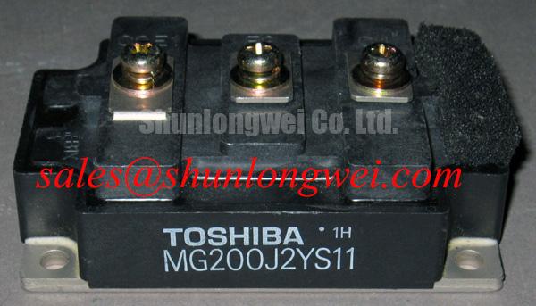
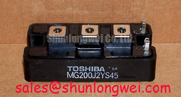
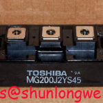
The MG200J2YS45 is a Toshiba IGBT module with a rated voltage of 1200 V and rated current of 200 A, both Official Specifications. Its stated package designation is Toshiba Module. Those ratings establish the initial comparison against an equipment bill of materials; they do not establish terminal arrangement, mounting dimensions, gate requirements, or suitability for a particular inverter. Check those details against the applicable Toshiba documentation and the equipment drawings before treating the part number as an installation match.
Start the gate-drive review at the equipment schematic, not at a proposed bias setting. A switching node can couple through an IGBT’s gate-to-collector capacitance and raise the gate voltage of a device intended to remain off. A low-impedance active Miller clamp is one possible driver-level response. Negative off-bias is another design consideration, but neither its required value nor the presence of a clamp is established by the stated MG200J2YS45 ratings. The system engineer should confirm the original driver topology and verify gate-voltage behavior during switching tests before changing either feature. The discussion of Evolution of Negative Off-Bias Gate Drive Circuits provides background for evaluating that trade-off; it is not a gate-bias specification for this module.
At incoming inspection, read the terminal designations on the module and compare them with the approved drawing. If that drawing identifies separate gate and emitter control connections, check continuity along the intended driver return path without assuming that a similarly shaped terminal has the same function on another Toshiba part. For a diode-mode measurement, use the documented device schematic to identify the expected conduction path first. Record meter polarity, displayed forward reading, and whether surrounding circuitry remains connected. A reading that differs from a known-good assembly warrants isolation and repeat measurement; a generic diode-drop threshold is not enough to accept or reject the module.
Bench Tip: Handle the gate terminals with ESD precautions and compare cold readings using the same meter, polarity, and circuit isolation as the known-good reference.
Once the driver is connected, examine the off-state gate waveform and the switching-node waveform together. A brief gate rise during the opposite device’s transition may point to coupling, return-path impedance, or probe placement; it does not, by itself, prove cross-conduction. As a Design Consideration, keep the driver return path short and its physical route deliberate to limit unwanted coupling, then confirm the result with appropriately rated probes under the equipment’s controlled test procedure. Creepage, clearance, and isolation arrangements must be checked against the actual assembly requirements rather than inferred from the 1200 V Official Specification.
Benchtop Waveform Tuning: Evaluating Switching and Thermal Stress on MG200J2YS45
A 200 A Official Specification is not a permission to apply that current under every pulse pattern or cooling condition. When reviewing an overload event, collect the measured current waveform, case-temperature record, switching conditions, and cooling configuration. The junction temperature can continue rising during a pulse even when the accessible case surface changes slowly. A transient thermal calculation is appropriate only when the relevant loss data and Toshiba thermal-impedance information are available for the exact device and test conditions. Without those inputs, a calculated peak junction temperature would carry false precision.
For bench comparison, capture the same operating transition before and after a driver or snubber change. Look at turn-off voltage overshoot alongside current and gate voltage, using a probe connection that does not add a large measurement loop. As an Engineering Recommendation, minimize parasitic loop inductance where turn-off overshoot is a concern, then verify peak voltage against the measured DC-link voltage and the module’s 1200 V Official Specification during controlled switching tests. The permissible operating margin is determined by the complete system and its applicable documentation, not by the voltage rating alone.
If the approved schematic confirms an associated freewheeling diode, inspect its commutation interval as well. Abrupt current change and voltage ringing can involve diode recovery behavior, wiring inductance, or both; a waveform captured at one location cannot separate those contributions reliably. Compare measurements at consistent points and operating conditions before altering a snubber. A snubber may change switching stress and noise, but its values require system-level validation, including thermal effects. No radiated-emissions compliance claim follows from fitting a particular snubber or from selecting this IGBT module.
In a traction inverter evaluation, the controller may regulate motor current in rotating coordinates. The Park transformation explains the direct-quadrature representation used in such control analysis. It does not replace measurements at the module terminals: controller current commands, phase-current waveforms, and individual switching events answer different diagnostic questions. For an electric forklift traction drive, check the actual inverter schematic and DC-link architecture before assessing whether the MG200J2YS45 fits the equipment.
Preventing Spurious Faults: Cosmic Ray Robustness and Voltage Derating Guidelines for MG200J2YS45
The stated 1200 V Official Specification supplies a voltage rating, not a published cosmic-ray failure rate or an altitude-derating curve. Terrestrial radiation and operating voltage can be relevant to high-voltage semiconductor reliability, but no device-specific single-event-burnout or failures-in-time figure is established by the supplied specifications. A fleet reliability estimate would need a qualified source and defined operating conditions. For a product-level repair decision, first determine the equipment’s actual DC-link voltage and capture switching peaks at the module terminals; unexplained faults should not be attributed to radiation without stronger evidence.
When an inverter reports intermittent trips, preserve fault logs and note the load, temperature, and bus-voltage conditions under which they occur. Check whether the protection input agrees with a measured electrical event, then inspect gate-drive supply behavior, connector seating, and voltage-sense paths against a known-good channel where available. These checks can distinguish a repeatable switching disturbance from a measurement-path problem, although neither result establishes the lifetime reliability of the module. As a Design Consideration, voltage headroom should be assessed using measured operating and transient conditions and the applicable manufacturer documentation; a universal derating percentage would not describe this installation.
Insulation testing needs similar discipline. Confirm the test points, applied procedure, and permitted test conditions from the module documentation and the equipment service instructions before connecting a withstand tester. The 1200 V device rating is not an insulation-test voltage, and a satisfactory result at one set of terminals does not certify the entire inverter’s isolation system. Record the setup and result so that later maintenance can compare like with like.
Preventing Spurious Faults: Multi-Module Parallel Current Sharing Guidelines for MG200J2YS45
If a repair drawing shows modules operating in parallel, confirm that each position calls for the same approved part and terminal arrangement before comparing static readings. Parallel operation cannot be approved from the 200 A Official Specification alone. It depends on the devices’ conduction and switching characteristics, thermal coupling, buswork, and gate-drive implementation. In particular, do not assume that the relevant on-state voltage has a beneficial temperature coefficient across the equipment’s operating range without device-specific data.
At the bench, measure each gate path and driver return path according to the schematic, then inspect power connections for differences in routing or contact condition. Under a controlled load test, compare branch-current waveforms with matched sensors and capture timing as well as amplitude. A current imbalance that appears chiefly during transitions may call for closer examination of gate-loop symmetry and bus parasitics; one that persists after the transition calls for a broader review of device and connection characteristics. These are diagnostic directions, not single-cause verdicts.
Replacement screening deserves the same restraint. The linked MG100Q1ZS40 is a separate Toshiba part to assess against its own documentation, not a verified direct replacement for MG200J2YS45. Compare ratings, circuit configuration, terminal map, mechanical fit, and driver requirements before proposing any substitution. Likewise, MG150Q1JS40 may be reviewed as a distinct module when mapping other positions in an equipment power stage; its role cannot be assigned from a neighboring part number. Finish the evaluation by recording the approved part number for each inverter position and the measured branch behavior under the equipment’s service test conditions.