

Content last revised on September 13, 2026
Logic Supply Voltage Sequencing (3.3V/5.0V) to Eliminate Driver IC Latch-Up Risks
The labels 3.3V and 5.0V should be treated as verification points, not as interchangeable supply options for the LTB190E1-L01. The system integrator should verify the required logic supply voltage, interface pin assignment, allowable power sequence, and timing limits from the original panel documentation and host-board schematic before energizing the replacement. Applying a supply voltage based only on connector appearance can create a mismatch at the panel interface.
For a display showing no image, partial image, or unstable startup behavior after replacement, inspect the power rails at the panel connector and compare their arrival order with a known-good installation where available. A scope capture can help establish whether the source board presents stable logic power and valid data before the display-enable path is asserted. This is an Engineering Recommendation for system validation rather than an official electrical rating of this panel.
Data-format alignment also matters. The source controller, cable assembly, and panel must agree on the required signaling standard and pixel-data arrangement. JEIDA and VESA mappings are not universally interchangeable, and a mismatch can present as unusual color ordering, a divided image, or other raster artifacts. Treat differential-pair impedance continuity, clock-pair integrity, and connector retention as a single signal path. 💡 Pro Tip: Keep paired display signal routes physically matched and verify the cable shield termination at the enclosure boundary to reduce pixel-clock disturbance.
Backlight supply, current regulation, enable control, and dimming behavior must likewise be confirmed from the host equipment documentation. Do not infer LED type, backlight lifetime, or a PWM frequency from this model designation alone. In a repair evaluation, observe brightness stability after thermal soak and inspect the driver output against the known-good signal path before assigning a fault to either the panel or the controller.
Grayscale Inversion Mitigation & Optimal Viewing Direction Alignment
Do not assume the liquid-crystal mode, viewing cone, surface finish, contrast ratio, or optical specifications of LTB190E1-L01 without the original factory optical documentation. These attributes are material to a replacement decision because a mechanically compatible panel can still produce an unacceptable image when the operator views it from a different vertical angle or under strong ambient illumination.
During bench acceptance, display neutral gray fields, fine text, single-pixel line patterns, and the equipment’s normal user interface. Observe the image from the operator’s expected position rather than only perpendicular to the screen. Tone reversal, inconsistent grayscale, or reduced readability may arise from panel optical characteristics, source timing, display settings, or the surrounding enclosure window. The observation should lead to further measurement, not a single-cause diagnosis.
For navigation bridge consoles and other equipment exposed to changing ambient light, the system designer should evaluate the complete optical stack: panel, bezel opening, cover lens, gasket, and illumination control. Surface reflections and enclosure geometry can materially affect readability. The LTB190E1-L01 should be assessed as the installed module, not as an isolated image surface.
High-Humidity Storage Margins (60°C / 90% RH) & Delamination Prevention Protocols
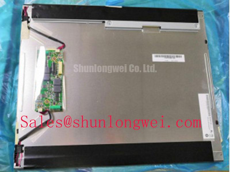
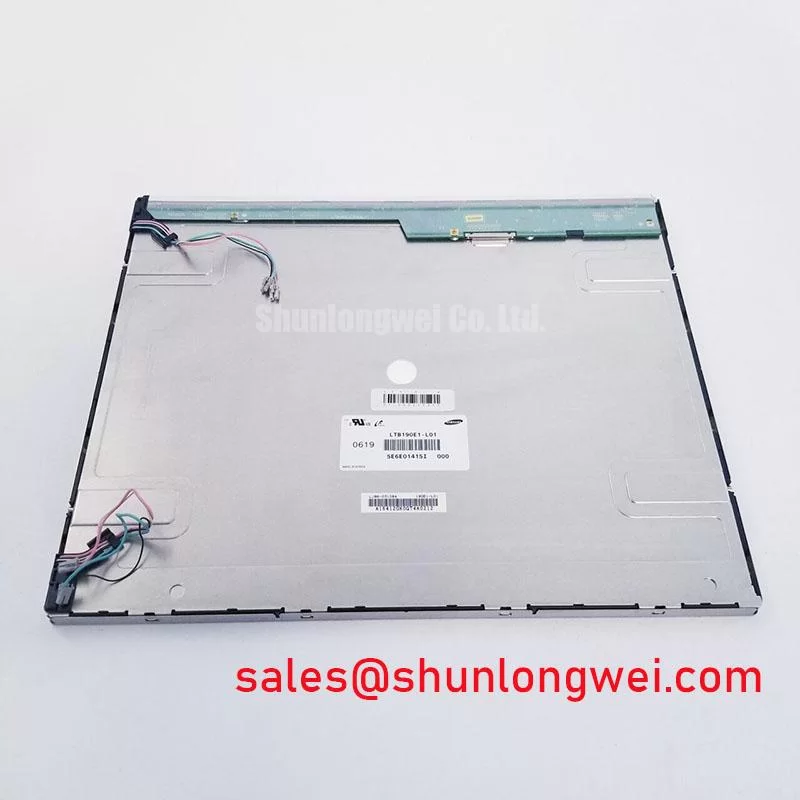
Temperature and humidity figures should not be assigned to this panel unless they are confirmed in the applicable factory documentation. Before installation, inspect the display perimeter, front surface, polarizer area, connector region, and mounting tabs for handling damage, contamination, or evidence that the unit was stored outside the host equipment’s controlled process. Use only the mounting hardware and retention arrangement specified by the equipment manufacturer.
Storage and installation practices are a Design Consideration. Avoid trapping moisture within the enclosure, avoid stressing the active display area during fitting, and confirm that cable routing does not apply a sustained side load to the connector. Where equipment operates through cold starts or wide temperature changes, validate image response and backlight behavior at the actual system limits. Slower apparent grayscale transitions can require investigation of the complete operating environment, including the panel, source board, power subsystem, and enclosure temperature.
For a broader engineering discussion of industrial display interfaces, environmental integration, and selection variables, see The Ultimate Guide to Industrial TFT LCD Technology. That reference supports evaluation planning; it does not replace the original documentation for the specific LTB190E1-L01 configuration.
Suppressing Pixel Jitter & Horizontal White Lines Induced by Adjacent 400V Motor Drives
If image noise appears only while nearby variable-frequency motor drives operate, begin with observation rather than replacement. Compare the display with the motor drive inactive and active, then inspect cable continuity, connector engagement, chassis bonding, and the routing relationship between the display harness and high-energy conductors. Pixel jitter or horizontal white lines may indicate coupled interference, an unstable supply, a marginal connection, or a source-side signal issue; use an oscilloscope against a known-good path where practical.
A shielded display cable terminated according to the host equipment’s grounding architecture is an Engineering Recommendation when common-mode interference is suspected. The objective is to control the signal return path and reduce coupling, while the final arrangement must be verified at system level. A power-input filter or ferrite strategy must also be selected and validated by the system engineer, because its effectiveness depends on cable geometry, enclosure bonding, driver noise spectrum, and source impedance.
When assessing an alternative display for a compatible industrial interface, engineers can review LQ201U1LW31 as a separate candidate and compare its official mechanical, electrical, and optical documentation against the original assembly. For related display-system sourcing research, LQ10D321 can be examined independently. Neither reference establishes drop-in compatibility with LTB190E1-L01; connector, timing, supply, mounting, and optical requirements remain system-determined.
For general power-quality context in industrial supply systems, consult Active Power Factor Correction (PFC) Circuits in Industrial Supplies and the IEC publication page for IEC 60076 Power Transformers. These are contextual references and do not constitute compliance, EMC, or reliability certification for this individual display module.