


Content last revised on April 2, 2026
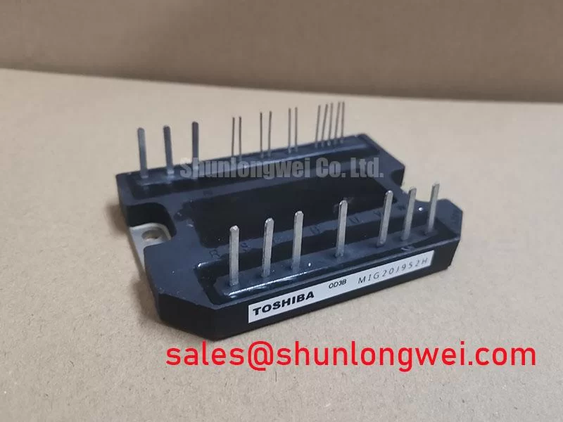
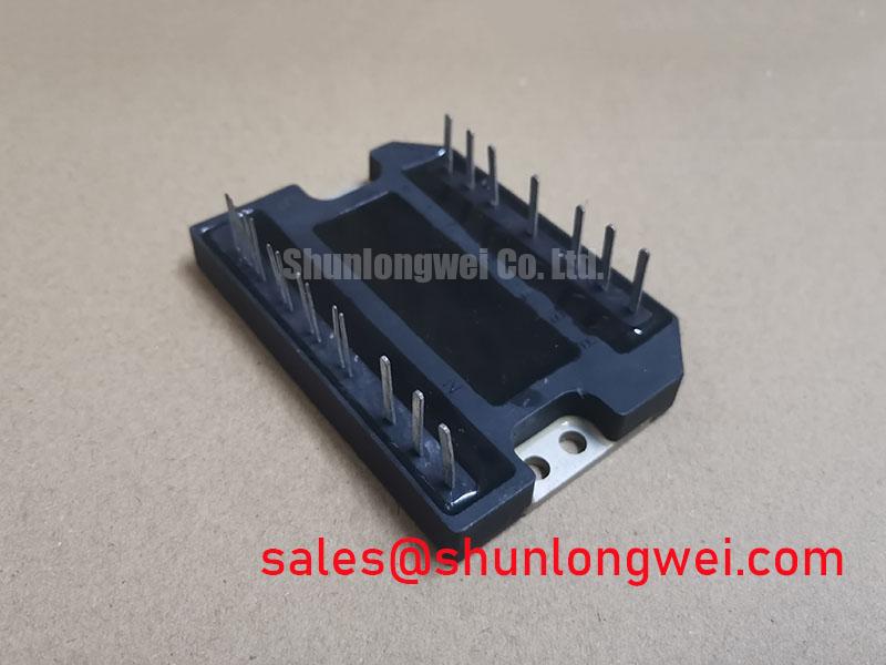
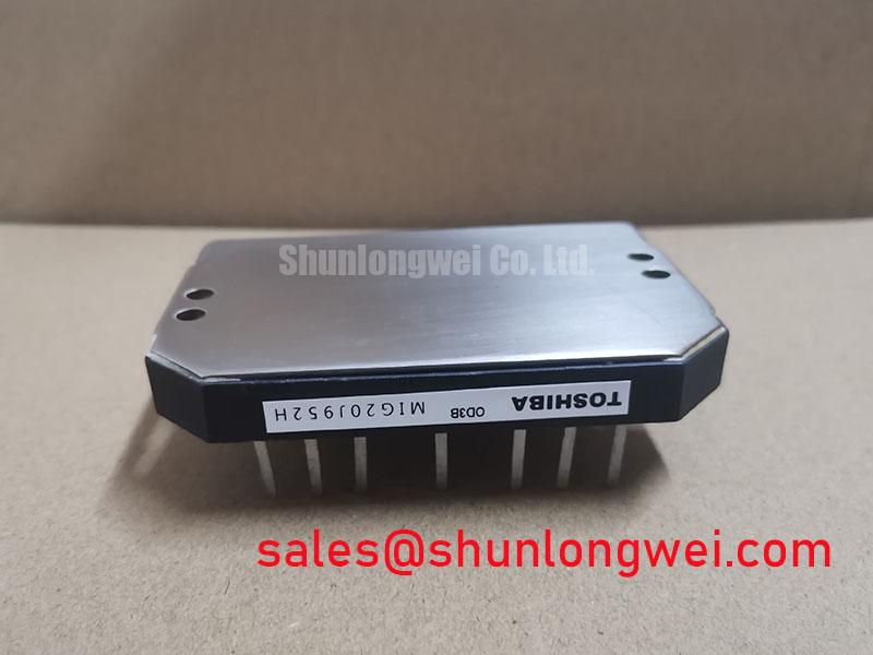
Toshiba MIG20J952H | High-Integration 7-in-1 IGBT PIM for Compact Motor Drives
For design engineers developing compact and cost-effective motor control systems, the Toshiba MIG20J952H stands out not merely as a component, but as a comprehensive power stage solution. This is not just a standard Insulated Gate Bipolar Transistor; it is a highly integrated Power Integrated Module (PIM) that combines a full three-phase inverter bridge with a dedicated brake chopper circuit into a single, robust package. It is engineered to streamline design, reduce assembly complexity, and enhance the reliability of low-to-mid power motion control applications.
Product Highlights at a Glance
- 7-in-1 Integrated Topology: Combines six 600V/20A IGBTs in a three-phase bridge and one brake chopper IGBT with their corresponding free-wheeling diodes (FWDs) in a single module.
- Design Simplification: Drastically reduces printed circuit board (PCB) footprint and component count compared to discrete solutions, accelerating time-to-market.
- Optimized for Motor Control: Engineered for the dynamic load conditions and inductive kickback inherent in robotic servo drives and Variable Frequency Drives (VFDs).
- Proven Reliability: Built within a rugged industrial package designed for superior thermal performance and long operational life.
Technical Deep Dive: The Value of Integrated Architecture
The core engineering advantage of the Toshiba MIG20J952H lies in its Converter-Inverter-Brake (CIB) topology. By co-packaging the essential power switching elements, Toshiba has addressed several critical design challenges simultaneously. Integrating the seven IGBTs and their associated FWDs minimizes the stray inductance in the power circuit loops. This is a significant benefit, as it reduces voltage overshoots during high-speed switching events, thereby simplifying the requirements for external Snubber Circuit design and improving overall electromagnetic compatibility (EMC) performance.
Furthermore, the module's construction ensures that all power devices are mounted on a single electrically isolated substrate. This simplifies thermal management by providing a unified heat path to the heatsink, leading to more predictable and uniform temperature distribution across the die. This contrasts sharply with discrete designs where thermal imbalances can lead to premature failure of individual components.
MIG20J952H Key Electrical Characteristics
The following parameters underscore the module's suitability for its target applications.
| Parameter | Value |
|---|---|
| Collector-Emitter Voltage (VCES) | 600 V |
| Collector Current (IC) | 20 A |
| Collector-Emitter Saturation Voltage (VCE(sat)) @ 20A | 2.7 V (Max) |
| Total Power Dissipation (PC) | 125 W |
| Operating Junction Temperature (Tj) | -40 to +150 °C |
Application Scenarios & Value Proposition
The specific design of the MIG20J952H provides tangible benefits across several key industrial sectors:
- Compact Variable Frequency Drives (VFDs): For AC motors up to ~3.7 kW, this PIM enables the creation of incredibly compact VFDs. The all-in-one design saves critical internal space, allowing for smaller enclosures and lower material costs.
- Robotics and CNC Servo Drives: In applications requiring precise motion control, the integrated brake chopper is essential for managing regenerative energy during rapid deceleration. The MIG20J952H handles this internally, simplifying the external circuitry and ensuring system stability.
- General Industrial Automation: For systems like pumps, fans, and conveyor belts, this module offers a "plug-and-play" power stage that is both robust and easy to implement, reducing engineering overhead for non-specialist teams.
By leveraging these integrated IGBT modules, engineering teams can focus on control logic and software, confident in the performance and reliability of the power electronics core.
Engineer's FAQ for the MIG20J952H
1. Is a negative gate voltage required for turn-off?
While the module can be operated with a 0V turn-off signal, it is best engineering practice to apply a small negative gate voltage (e.g., -5V to -10V). This provides a stronger buffer against parasitic turn-on caused by high dV/dt during the switching of other devices in the bridge, significantly enhancing system noise immunity and preventing potential shoot-through events.
2. What are the key thermal management considerations?
Achieving the rated performance of the MIG20J952H is critically dependent on effective Thermal Management. Ensure the heatsink surface is flat (typically within 50µm) and clean. Use a high-quality Thermal Interface Material (TIM) to minimize the thermal resistance between the module's baseplate and the heatsink. Proper mounting torque, as specified in the datasheet, is crucial to avoid warping the baseplate and creating thermal voids.
For detailed application support or to discuss volume pricing for your project, please contact our technical team today.